@Jamin Grounds are already shared through that power board.
@hgomez809 I don’t see any reason why it wouldn’t work on the 5v… unless that board has a faulty 5v regulator?? Can you test it with a meter?
@Jamin Grounds are already shared through that power board.
@hgomez809 I don’t see any reason why it wouldn’t work on the 5v… unless that board has a faulty 5v regulator?? Can you test it with a meter?
You should really be only using 5v power… the MCU requires at least 4.5v… and you’re just feeding in 3.3v.
My opinion… switch to 5v completely and you wont have problems.
@hgomez809 But make sure you are feeding that 5v into the Vin pin (@jamin correct me if I am wrong), not the currently used 3.3v pin ![]()
Same result after using 5v to power the mcu. The part i dont understand is that the relay didnt want to work with 3v earlier and now is the other way around!?
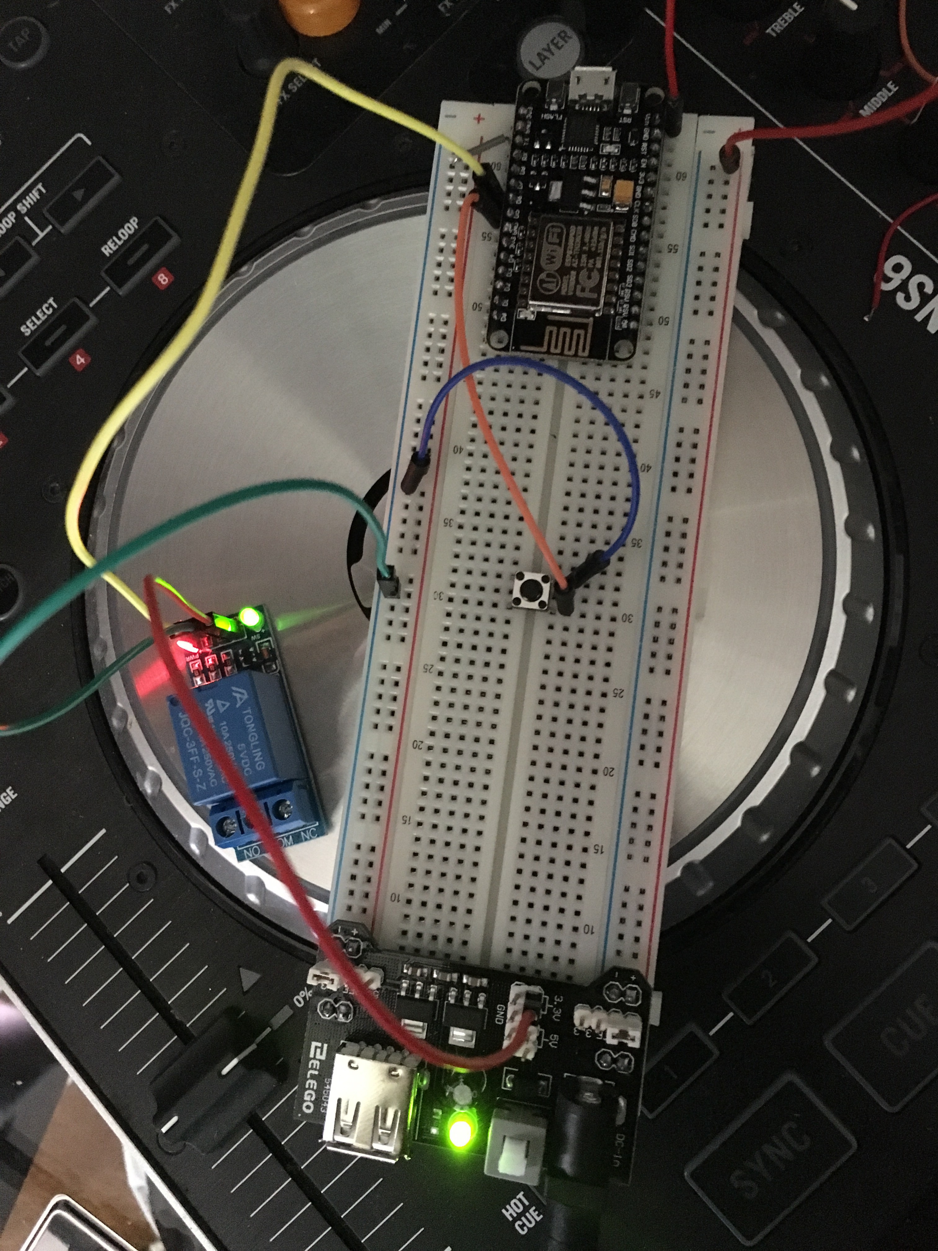
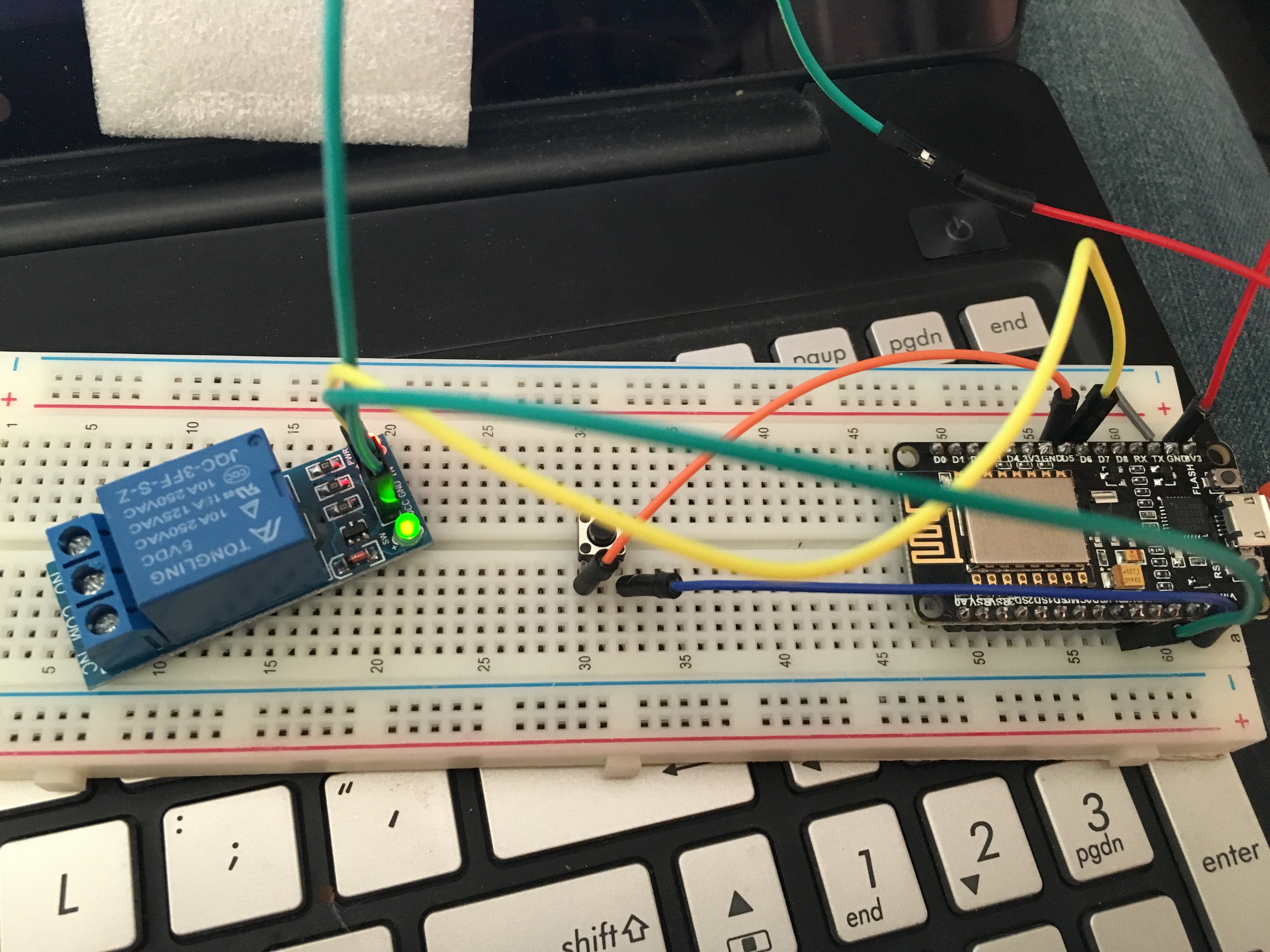
Just doing a simple wiring diagram for you now… just for you to reference to,.
Should be as simple as this to connect.
@hgomez809 I trust that the metallic looking “scratch” thingy that your relay is sitting on is not conductive?
try again now… made the project public
That is how i have it set up, however the relay is not clicking on the 5v, but as soon as i switch it to the 3.3v pin it works fine
Can you confirm the voltages with a meter? Also, what are you powering the Power Supply with?
Random…
I think there is something else going on.
Do you have any other relays to test with? They can be more than 1 chan for testing.
@Gunner well that won’t be happening anytime soon, since i just burned the power board while trying to get the reading with the metter lol. I will get another one tomorrow.
Edit: i was powering the power board with a 12v dc power adapter.
@Jamin i do have another one, but i will have to wait till tomorrow to test them out.
I will keep you updated
Oh my… it just never ends… Sorry to hear about that.
PS, by meter, I meant the one on the right ![]()

You got jokes huh haha
That is okay, thats how i learn. I bet you i won’t burn another one. At least not of the same power boards, not so sure about other boards 
Btw i am looking for some kind of splitter. To split my positive ac line into 2. I want to do it as neet and safe as possible for long term funtionality. Not trying to just twiste some cables together and put black tape around it.
I know i have seen these splitters, but cant seen to find them right now. Do you know the name?
@Jamin thank you that is exactly what i was looking for!
okay i know this is going to sound stupid, but i uploaded the sketch to another mcu board i just got and set up the breadboard for this new board and now it is not working. The mcu doesn’t even connect to the blynk server nor the wifi network for that matter?
I don’t really understand how it can be messep up.
Right now its only the board powered through the micro-usb, but that should not keep it from connecting to the internet.
Here is the code in case you guys are able to see any error with it?
#include <ESP8266WiFi.h>
#include <BlynkSimpleEsp8266.h>
#include <SimpleTimer.h>

#define VPIN V2

char auth[] = "Token";

// Your WiFi credentials.
// Set password to "" for open networks.
char ssid[] = "Wifi Name";
char pass[] = "Password";

void lightOn();
void lightOff();

boolean LampState = 0;
boolean SwitchReset = true;

const int TacSwitch = D5;
const int RelayPin = D6;

SimpleTimer timer;
WidgetLED VLED(V11);

void setup()
{
  Serial.begin(115200);
  pinMode(RelayPin, OUTPUT);
  pinMode(TacSwitch, INPUT_PULLUP);
  delay(10);
  digitalWrite(RelayPin, LOW);
  Blynk.config(auth);
  timer.setInterval(100, ButtonCheck);
}
void loop()
{
  Blynk.run();
  timer.run();
}
void ButtonCheck() {
  boolean SwitchState = (digitalRead(TacSwitch));
  if (!SwitchState && SwitchReset == true) {
    if (LampState) {
      lightOff();
    } else {
      lightOn();
    }
    SwitchReset = false;
    delay(50);
  }
  else if (SwitchState) {
    SwitchReset = true;
  }
}
void ToggleRelay() {
  LampState = !LampState;
  if (LampState) {
       lightOn();
  }
  else lightOff();
}
void lightOn() {
    digitalWrite(RelayPin, LOW);
    LampState = 1;
    Blynk.virtualWrite(VPIN, HIGH);
    VLED.off();
}
void lightOff() {
    digitalWrite(RelayPin, HIGH);
    LampState = 0;
    Blynk.virtualWrite(VPIN, LOW);
    VLED.on();
}
BLYNK_WRITE(VPIN) {
  int SwitchStatus = param.asInt();
    if (SwitchStatus == 2){
    ToggleRelay();
  }
  else if (SwitchStatus){
    lightOn();
  }
  else lightOff();
}
Hmm nothing looks out of place… what does your Serial output with Blynk debug enabled.
http://docs.blynk.cc/#blynk-firmware-debugging-define-blynk_debug
#define BLYNK_PRINT Serial
I am not sure if I am doing it right,
I copied this into the code
#define BLYNK_PRINT Serial // Defines the object that is used for printing
#define BLYNK_DEBUG        // Optional, this enables more detailed prints
after uploading the code to the board all I get back in the “serial monitor” is a bunch of squares and triangles as if the code is encrypted.
I might of found what was wrong.
changed
Blynk.config(auth);
for
Blynk.begin(auth, ssid, pass);
which I believe now the code is telling the mcu to begin the blynk connection by reading the token the wifi name and the password.