Light control over wifi blynk app as well as physical on off button?

Remove the power wire to the switch (on the right) and replace the resistor with same wire (but make sure it is on the ground, not the positive rail). Then rotate the button 45 degrees either direction to orient the pins properly so that pressing the button grounds out the D1 pin (brings it LOW as the code appears to desire).

If rotating the button makes it not fit properly, then just leave it where it is and wire ground and D1 so that they short out (according to the RED line I indicated earlier)… either side of the button is fine, just as long as both connections are on the same side.

Re-submit a new picture if you are still having issues.

No luck still, attached is a picture for confirmation.

Thank you!

Move the orange wire to the same side of the button as the blue (although the way you have it should have the LED on all the time if the code is correct)… I honestly haven’t looked at the code side of it :wink:

It still does not work

I am glad we are not trying to defuse a bomb :stuck_out_tongue:

Move the orange wire to the OTHER pin on the same side as the blue :wink:

However it clearly appears that your code also needs checking…

5 Likes

I am also glad :grin:

Anyways, is this correct? If so, still no luck.

And in concern to the code. Can you point out the areas that need to be fixed?

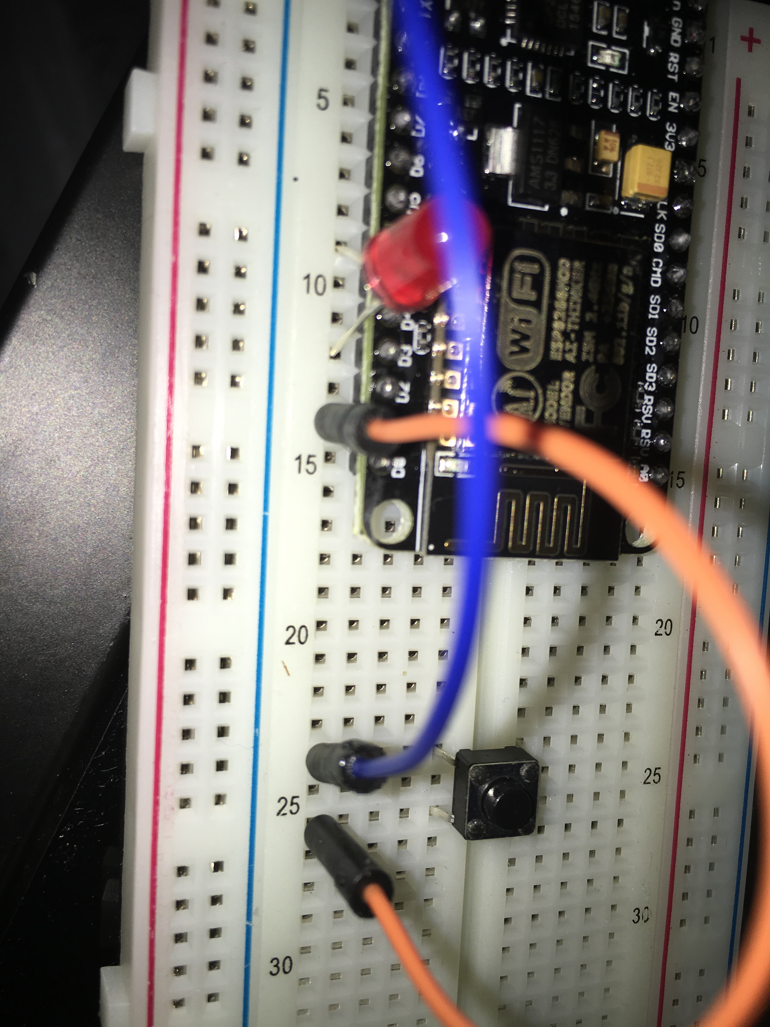
I also tried this code ( changed pins to D1 and D3 to match my connections) with no no luck regarding the physical button and same result regerding the app. Yes i tried a different button just in case

1 Like

Well, the wiring seems ok now… Just to be sure, you could switch the BLUE wire to 3.3v… in case I am reading the code wrong and the button needs to be brought HIGH to work.

I will have to spend some time looking at the code (quickly reading and analysing code is not my forte).

And I do not have any ESP boards to test it on (in fact I just realised I needed to install new board support into my IDE just so I can compile ESP code… I live in the dark ages it seems :stuck_out_tongue_winking_eye: ).

I will look into it when I can, but perhaps someone else will have chimed in by then.

@hgomez809 By the way… I just noticed that you have also asked for assistance with the same issue on two other threads… we (in the community) prefer if people didn’t do that (we call it spamming)… keep same issue too one thread at a time please.

another problem is that you apparently did not use any protective resistor on the led. so there are chances that you already fried the digital pin on the esp… and this is why not working. in your final project i understand you would like to use a relay. this will not work this way. you will need a mosfet or ss relay for the task.

afaik, these pins are not designed for supplying more than ~10-12mA. but if you are hooking up directly a led or relay like that, that can draw more. the digital pin should be protected with a 300 ohms resistor at least.

but sincerely and without offense, reading through these posts, i would highly recommend to you, to stop right now all these experiments, and take some time to learn about electronics and programming. even a simple task like this needs some basic knowledge.

do some electronics and arduino tutorials on youtube or arduino website, otherwise you can damage the components and just be frustrated about the lack of a feeling of success…

Good points! @wanek I was unaware that these ESP boards are so under powered on the pins… I commonly do tests with bare LEDs on my Arduinos at 5v (I know I shouldn’t but sometimes can’t find my pre-wired LEDS :wink: )

However, I was understanding that he had the Blynk widget button lighting up the LED just fine all this time? Perhaps not?

Isn’t the problem with the code in this function?

void checkPhysicalButton()
int btnPin1State = LOW; // ON
int RelayPin1State = HIGH; // OFF

You’re calling the function every 100ms but it’s not actually checking the state of the button attached to Pin 1, its writing LOW to Pin1 and HIGH to Pin3 each time it’s called.
Shouldn’t it be:

if (int btnPin1State = LOW)
{
int RelayPin1State = HIGH;
}

Pete.

I also noticed that statement looked strange… It is not bracketed off with { }, and situated before the setup loop… but then for all I know that is particular of how ESP code variations work?? Seems to compile when I tried.

My point was that it’s missing an ‘if’ statement, so it doesn’t matter if the button is pressed or not, it always switches the relay to off every 100ms.

What the OP is actually doing is building the equivalent of a sonoff device. As you can buy these for a few Pounds/Dollars/Euros and flash the esp8266 with your own code, it doesn’t seem worth building your own.

There’s Blynk and MQTT integration here https://github.com/tzapu/SonoffBoilerplate/blob/master/SonoffBoilerplate.ino

Pete

1 Like

Hi guys,
@PeteKnight probobly something glitch from the functions, @hgomez809 just cross check again the original post. That code is working perfectly for arduino uno and atmega2560. @speed57 is using this code now since i share thesames sketch. I re view you modified sketch for esp pmce i have freel time. Im out of town by the way.

1 Like

Sory for the speeling om just typing using my mobile… :blush:

/** I will review your modified sketch for esp once i have free time. Im out of town by the way.**/

Upon actually looking at the code a bit closer, I realised that because those three lines are in the pre-setup position, it doesn’t matter about either the missing brackets or the “if” statement… it is just a one shot call of the void checkPhysicalButton() (assuming it even calls the function - it may do nothing where it is placed).

And the other two lines are setting up the variables for btnPin1State & RelayPin1State
Doh… I should have realised that earlier… too sleepy :blush:

As for why the button is not working… or even if anything else works or not… I think I will just watch and see what others say… it’s nap time for me :slight_smile:

Well technically what he is doing is learning by trial and error… and I can’t fault that :wink:

This for me

void checkPhysicalButton()
int btnPin1State = LOW;// ON
int RelayPin1State = HIGH; // OFF

Is equivalent as

void checkPhysicalButton()
{
   int btnPin1State = LOW;// ON
} 
int RelayPin1State = HIGH; // OFF

So relay RelayPin1State becomes a global variable, this is how the if statement works when omitting brackets, I wonder if the function declaration acts the same?

1 Like

Okay, I finally decided drag out some hardware and look at it properly.
It’s now working for me with the code exactly as posted. The problem is with the way that the pins on the NodeMCU are referenced by the sketch.
Pin 4 (where the anode of the LED connects) isn’t Digital Pin 4, but the 4th pin up on the right hand side. Labelled RX on my board.
In the same way, the switch connects between Ground and the 3rd pin up on the right hand side - labelled TX, not Digital Pin 3 on the board.

Hope this makes sense!

Pete.

2 Likes

Thank you PeteKnight, it makes some sence, however would it be possible for you to upload a picture of your set up?