Hi everyone,
At first sorry for my bad english cause i’m french, i’ll do my best.
i need your help for my simple project
i would like to write a message with de text input widget on a physical LCD 16x2. No problem. BUT i would like to “switch off” le LCD with lcd.nobacklight() and lcd no.display() when i push a button.
I tried (really) about 70 times with different code… No way i can’t find how to do,
So please help me… nothing happened when i push the button.
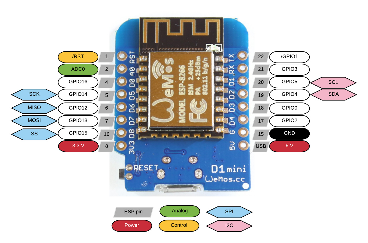
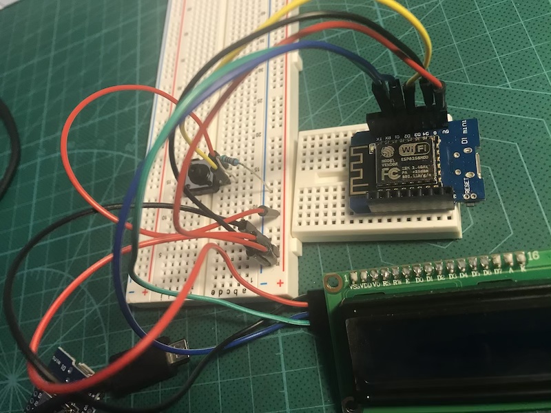
I’m working on wemos mini, lcd16x2 linked in I2C, arduino IDE , simple button with a 220 resistor.
here is the code. thank you for your help
/* Comment this out to disable prints and save space */
#include <LiquidCrystal_I2C.h> // bibliothèque ecran I2C
#include <Wire.h> // bibliothèque I2C
LiquidCrystal_I2C lcd(0x3F, 16, 2);
#define BLYNK_PRINT Serial
#include <ESP8266WiFi.h>
#include <BlynkSimpleEsp8266.h>
// You should get Auth Token in the Blynk App.
// Go to the Project Settings (nut icon).
char auth[] = "help me";
char ssid[] = "help me";
char pass[] = "help me";
int etatbouton = 0;


void setup()
{
  lcd.begin();
  lcd.backlight();

  pinMode(3, INPUT);

  Serial.begin(9600);
  Blynk.begin(auth, ssid, pass);

  Serial.print("Blynk Ready\n");
}
  BLYNK_WRITE(V0) {
    lcd.clear();
    String textIn = param.asStr();
    Serial.print(textIn + "\n");
    lcd.setCursor(0, 0);
    lcd.print(textIn);

    etatbouton=digitalRead(3);
    if (etatbouton == HIGH) {
      Serial.println("appui");
      lcd.noBacklight();
      lcd.noDisplay();
    }
      else{
        Serial.println("pas d'appui");
        lcd.backlight();
        lcd.display();
      }
  }


void loop() {

  Blynk.run();

}
When it comes to choosing which pin to use, you should read this:
If your Wemos is a D1 Mini then you should also use this table to translate GPIO numbers used in the link (and in your code) in to the “D” numbers printed on to your board:
But i really need for my project that a physical button activate or deactivate the display.
In fact, this button il connected to a lid of a box, then when the lid is open, it activate the display and deactivate it when you close the box…
Do you have any idea for it?
with an arduino UNO no problem to do it, but with blynk and wemos i can’t do do it unfortunately.
What type of widget do you have attached to V0 in your app, how is it configured, and what role does this play in your process?
At the moment, your code won’t read the state of your physical switch unless the value of V0 changes, either because the user makes this change in the app, or because the widget is set to push its value on a regular basis.
Hi Pete,
Thank you again for your answer.
I use the “text Input” widget, and connected it as you said before at V0.
the effect is when i write a texte in this widget it write this text on my physical display.
i need for my project that a physical button activate or deactivate the display.
In fact, this button il connected to a lid of a box, then when the lid is open, it activate the display and deactivate it when you close the box…
do you think i have to put this part of sketch in the loop ?( i already tried it):
Hi Pete thank you again for your answer,
So i modified the sketch with your recommandation as you can see below but it doesn’t work unfortunately.
and in serial i don’t see “appui” or " pas appui".
only the text i’ve write in the widget is on the display and on the serial.
Thank you for your patience, really thank you.
Can you check what i’ve done please?
/* Comment this out to disable prints and save space */
#include <LiquidCrystal_I2C.h> // bibliothèque ecran I2C
#include <Wire.h> // bibliothèque I2C
LiquidCrystal_I2C lcd(0x3F, 16, 2);
#define BLYNK_PRINT Serial
#include <ESP8266WiFi.h>
#include <BlynkSimpleEsp8266.h>
#include <SimpleTimer.h>
// You should get Auth Token in the Blynk App.
// Go to the Project Settings (nut icon).
char auth[] = “help”;
char ssid[] = “help”;
char pass[] = “help”;

SimpleTimer timer;
int etatbouton = 0;

void checkbouton(){

etatbouton=digitalRead(D4);
if (etatbouton == HIGH) {
Serial.println(“appui”);
lcd.noBacklight();
lcd.noDisplay();
}
else{
Serial.println(“pas d’appui”);
lcd.backlight();
lcd.display();
}
}

void setup()
{
lcd.begin();
lcd.backlight();

pinMode(D4, INPUT);
// Debug console
Serial.begin(9600);
Blynk.begin(auth, ssid, pass);

Serial.print(“Blynk Ready\n”);
}
BLYNK_WRITE(V0) {
lcd.clear();
String textIn = param.asStr();
Serial.print(textIn + “\n”);
lcd.setCursor(0, 0);
lcd.print(textIn);
}

void loop() {

Blynk.run();
timer.setInterval(500, checkbouton);

}
i can see in the serial " appui" and my display is in nodisplay() and noBacklight()
But when i push the button, the state doesn’t change , it stays in the state i describe you before
her is my correction with your help:
As I explained in my last post, this line needs to be in void setup() not void loop()
When you’re posting code, you need to put triple backticks at the beginning and end of your code so that it displays correctly - I’ve fixed your last couple of posts.
oh thanks Pete,
i haven’t find the “backticks” traduction but now i know what it is.
I corrected it in my upper sketch and download it right now but it doesn’t change…
i am always in “appui” state with nobacklight and nodisplay state and when i push the button nothing changes
here is my correction: