Hello first time to post here. I have an issue right now I am using a mq137 sensor which requires 5v which made me use arduino uno to to make it work now I was tasked to create an app so that we can monitor it online hence using nodemcu. I connected my arduino uno and nodemcu using serial connection so that nodemcu receives the data from the arduino uno and then send it to blynk, Here comes the problem both the arduino uno and nodemcu have the same output in the serial but in the blynk app it doesn’t show the correct value.
Attached here is my code and circuit diagram:
arduino code:
#include <SoftwareSerial.h>
int gas_sensor = A0; //Sensor pin
float m = -0.263; //Slope
float b = 0.42; //Y-Intercept
float R0 = 20; //Sensor Resistance in fresh air from previous code
int relay1 = 13; // relay
int relay2 = 12; // relay

SoftwareSerial mySerial(2, 3); // RX, TX pins on Arduino Uno

void setup() {
  mySerial.begin(9600); // Initialiaze SoftwareSerial communication at 9600 baud
  Serial.begin(9600);   // Initialize the built-in serial communication for debugging
  pinMode(relay1, OUTPUT);
pinMode(relay2, OUTPUT);
digitalWrite(relay2, HIGH);
digitalWrite(relay1, HIGH);
pinMode(gas_sensor, INPUT);
}

void loop() {
   float sensor_volt; //Define variable for sensor voltage
  float RS_gas; //Define variable for sensor resistance
  float ratio; //Define variable for ratio
  float sensorValue = analogRead(gas_sensor); //Read analog values of sensor
  sensor_volt = sensorValue * (5.0 / 1023.0); //Convert analog values to voltage
  RS_gas = ((5.0 * 10.0) / sensor_volt) - 10; //Get value of RS in a gas
  ratio = RS_gas / R0; // Get ratio RS_gas/RS_air

  double ppm_log = (log10(ratio) - b) / m; //Get ppm value in linear scale according to the the ratio value
  double ppm = pow(10, ppm_log); //Convert ppm value to log scale
  double percentage = ppm / 10000; //Convert to percentage


  String ppmString = "PPM " + String(ppm);
  mySerial.println(ppmString);

  // Print the sensor data to the Arduino Uno's serial monitor
  Serial.print("MQ137 Sensor Data: ");
  Serial.print("PPM: ");
  Serial.println(ppm);
   if(ppm < 2)  {

    digitalWrite(relay1, HIGH);
    digitalWrite(relay2, HIGH);
    delay(1000);

  }
  else if(ppm >= 2 && ppm <= 10 ) {

    digitalWrite(relay2, HIGH);
    digitalWrite(relay1, LOW);
    delay(1000);

  }
  else if (ppm > 10) {

    digitalWrite(relay1, HIGH);
    digitalWrite(relay2, LOW);
    delay(1000);
  }

}
esp8266 code:
#define BLYNK_TEMPLATE_NAME "mq137"
#define BLYNK_AUTH_TOKEN "woSKw8i8qW-OG_lTWSi1rAf5wzBc-XEK"

#include <SoftwareSerial.h>
#include <ESP8266WiFi.h>
#include <BlynkSimpleEsp8266.h>

// NodeMCU pins for SoftwareSerial
SoftwareSerial mySerial(D7, D8); // RX (D7) and TX (D8) pins on NodeMCU

// Blynk authentication token and Wi-Fi credentials
char auth[] = "woSKw8i8qW-OG_lTWSi1rAf5wzBc-XEK"; // Replace with your Blynk authentication token
char ssid[] = "homewifi";       // Replace with your Wi-Fi SSID
char pass[] = "123456789";   // Replace with your Wi-Fi password

String receivedData = "";  // Initialize a String to store received data
BlynkTimer timer;
void myTimer()
{
  // This function describes what will happen with each timer tick
  // e.g. writing sensor value to datastream V5
  Blynk.virtualWrite(V0, receivedData);
}
void setup() {
  Serial.begin(9600);
  delay(100);
  mySerial.begin(9600);
  delay(100);
  Blynk.begin(auth, ssid, pass);
  timer.setInterval(1000L, myTimer);
}

void loop() {
  Blynk.run();

  // Check if data is available on the SoftwareSerial connection
  if (mySerial.available()) {
    char receivedChar = mySerial.read();
    receivedData += receivedChar; // Concatenate received data

    // Check if a newline character is received (end of data packet)
    if (receivedChar == '\n') {
      Serial.print("Received Data: ");
      Serial.println(receivedData); // Print the complete data packet

      // Example: You can send the received data to Blynk
      Blynk.virtualWrite(V0, receivedData); // Replace V0 with the desired virtual pin

      // Clear the received data for the next packet
      receivedData = "";
      delay(500);
    }
  }

  // Add other code or delay as needed
  timer.run();
}
circuit diagram:
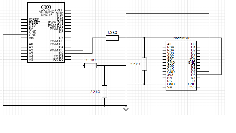
any help would be appreciated and thank you for reading it.
in my diagram i didn’t include the mq137 since it’s not available at Circuit Diagram Web Editor (circuit-diagram.org) but it’s connection is just 5v ground and A0(in the arduino uno)
tried to post the output but it seems that I’m not allowed yet