Issue when using lcd widget and physical lcd

Greetings:

I’m new to blynk currently i’m working on a project with Arduino Uno, I used Esp 01 to connect the Arduino to internet.

I want to display the results on both I2C lcd and lcd widget, but it doesn’t work for some reason :thinking:, .

I get connected to Blynk server and a led (on, off) so the ESP is working correctly, then tried to print in lcd widget and it worked ( i got the print on the app) and tried the I2C LCD that i have and it’s working as well.

The problem is when combined both LCD and lcd widget I got the first print on LCD and the widget doesn’t print anything!! And the ESP stay connected to blynk server for seconds (`in blynk app shows that your device is offline).

I couldn’t find out the reason for this conflict, I tried to find which command the conflict starting with, so I deleted every command required for LCD to work then added them one by one, turns out it’s the command to declare the address for LCD.

LiquidCrystal_I2C lcd (0x27, 16, 2).

This is the code

// See the Device Info tab, or Template settings
#define BLYNK_TEMPLATE_ID           "TEMPLATE_ID "
#define BLYNK_DEVICE_NAME           "DEVICE_NAME  "
#define BLYNK_AUTH_TOKEN            "AUTH_TOKEN  "


// Comment this out to disable prints and save space
#define BLYNK_PRINT Serial


#include <ESP8266_Lib.h>
#include <BlynkSimpleShieldEsp8266.h>

char auth[] = BLYNK_AUTH_TOKEN;

// Your WiFi credentials.
// Set password to "" for open networks.
char ssid[] = "network_ssid";
char pass[] = "password";

// Hardware Serial on Mega, Leonardo, Micro...
//#define EspSerial Serial1
char dat[] = "hello";
// or Software Serial on Uno, Nano...
#include <SoftwareSerial.h>
SoftwareSerial EspSerial(2, 3); // RX, TX
#include <Wire.h> 
#include <LiquidCrystal_I2C.h>
LiquidCrystal_I2C lcd(0x27, 16, 2);
// Your ESP8266 baud rate:
#define ESP8266_BAUD 38400

ESP8266 wifi(&EspSerial);

BlynkTimer timer;


// This function sends Arduino's up time every second to Virtual Pin (5).
// In the app, Widget's reading frequency should be set to PUSH. This means
// that you define how often to send data to Blynk App.
void myTimerEvent()
{
  // You can send any value at any time.
  // Please don't send more that 10 values per second.
  
  Blynk.virtualWrite(V5, dat);//millis() / 1000 
 Blynk.virtualWrite(V0, 58.9);      //random to test on blynk app
lcd.print("test");

}

void setup()
{
  // Debug console
  Serial.begin(115200);
lcd.begin();   
 lcd.backlight();
 lcd.clear();
lcd.print("test1");
  // Set ESP8266 baud rate
  EspSerial.begin(ESP8266_BAUD);
  delay(10);


  Blynk.begin(auth, wifi, ssid, pass);


  // Setup a function to be called every second
  timer.setInterval(1000L, myTimerEvent);
}

void loop()
{
  Blynk.run();
  timer.run(); // Initiates BlynkTimer
 
}

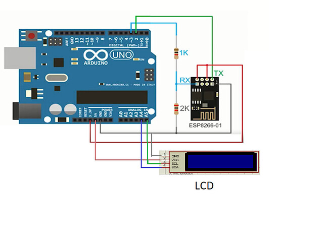
and the connection as shown below:

I appreciate any ideas best regards.
I’m surprised that this actually works, and I’d be even more surprised if it continues to work consistently over a period of time.
You should read this…

I think it would be useful if you posted both of these sketches.

It would also be useful if you told us whether you are using the LCD widget in simple or advanced mode, and which virtual datastream it’s attached to.

Pete.

Thakns for fast response.

This is to control a led using Blynk app,I connected a led to pin 4.

#define BLYNK_TEMPLATE_ID           "TEMPLATE_ID "
#define BLYNK_DEVICE_NAME           "DEVICE_NAME  "
#define BLYNK_AUTH_TOKEN            "AUTH_TOKEN  "


// Comment this out to disable prints and save space
#define BLYNK_PRINT Serial


#include <ESP8266_Lib.h>
#include <BlynkSimpleShieldEsp8266.h>

char auth[] = BLYNK_AUTH_TOKEN;

// Your WiFi credentials.
// Set password to "" for open networks.
char ssid[] = "network_ssid";
char pass[] = "password";

// Hardware Serial on Mega, Leonardo, Micro...
//#define EspSerial Serial1

// or Software Serial on Uno, Nano...
#include <SoftwareSerial.h>
SoftwareSerial EspSerial(2, 3); // RX, TX

// Your ESP8266 baud rate:
#define ESP8266_BAUD 38400

ESP8266 wifi(&EspSerial);

void setup()
{
  // Debug console
  Serial.begin(115200);
  // Set ESP8266 baud rate
  EspSerial.begin(ESP8266_BAUD);
  delay(10);


  Blynk.begin(auth, wifi, ssid, pass);
}

void loop()
{
  Blynk.run();
  
 
} 

I put button widget and created digital data stream and connected it to Pin 4 ( D4).

and this for print on lcd widget in simple mode:


// Template ID, Device Name and Auth Token are provided by the Blynk.Cloud
// See the Device Info tab, or Template settings
#define BLYNK_TEMPLATE_ID           "TEMPLATE_ID"
#define BLYNK_DEVICE_NAME           "DEVICE_NAME"
#define BLYNK_AUTH_TOKEN            "AUTH_TOKEN "


// Comment this out to disable prints and save space
#define BLYNK_PRINT Serial


#include <ESP8266_Lib.h>
#include <BlynkSimpleShieldEsp8266.h>

char auth[] = BLYNK_AUTH_TOKEN;

// Your WiFi credentials.
// Set password to "" for open networks.
char ssid[] = "ssid ";
char pass[] = "password";


// Hardware Serial on Mega, Leonardo, Micro...
//#define EspSerial Serial1
//char dat[] = "sssad";
// or Software Serial on Uno, Nano...
#include <SoftwareSerial.h>
SoftwareSerial EspSerial(2, 3); // RX, TX

// Your ESP8266 baud rate:
#define ESP8266_BAUD 38400

ESP8266 wifi(&EspSerial);

BlynkTimer timer;


// This function sends Arduino's up time every second to Virtual Pin (5).
// In the app, Widget's reading frequency should be set to PUSH. This means
// that you define how often to send data to Blynk App.

void sendSeconds() {
  Blynk.virtualWrite(V0, millis() / 1000);
}
void sendMillis() {
  Blynk.virtualWrite(V5, millis());
}
void setup()
{
  // Debug console
  Serial.begin(115200);

  // Set ESP8266 baud rate
  EspSerial.begin(ESP8266_BAUD);
  delay(10);


  Blynk.begin(auth, wifi, ssid, pass);
  
  // Setup a function to be called every second
  timer.setInterval(1000L, sendSeconds);
  // Setup a function to be called every second
  timer.setInterval(1000L, sendMillis);
}

void loop()
{
  Blynk.run();
  timer.run(); // Initiates BlynkTimer
 
}```

For the Lcd widget the first line attached to virtual datastream (V5),
and the second line attached to virtual datastream (V0)

I’ll change it to 9600

Power issue? You are feeding the Esp + the LCD from the Arduino board…

1 Like

I don’t think so because it’s working when i try to control a led (everything still connected all I do is changing the code).

And re-configured your ESP-01 to work at the same baud rate?
Have you re-tested your Blynk only sketch since you did this?

I think we’re still missing a part of the puzzle here.
You seem to have said that you’ve used a non-Blynk sketch to test that your I2C physical LCD is working correctly, but you haven’t shared that sketch.

When you’re using a non-Blynk sketch the ESP-01 is not being initialised and asked to connect to your WiFi system, so it’s not drawing the current that it does when you run your Blynk sketch.
I think that @psoro is probably right that your Uno can’t supply enough current to power both the ESP-01 in active mode and the LCD display. Because of this the sketch can’t locate the LCD display on the bus at address 27.

You need an external power supply for your peripherals, with a common GND to your Uno if you wnat to prove or disprove this theory.

Pete.

That’s for sure I’m on it.

I misunderstood what you meant by two sketches:

const int echoPin = 7;


long duration;
int FirstDistance=0,m=4;
bool s = false;
int SecondDistance=0;
double speed=0;
int distance=1;
float Time = 2.0;
float delayedtime = 1000*Time;
#include <Wire.h> 
#include <hd44780.h>
#include <hd44780ioClass/hd44780_I2Cexp.h>
hd44780_I2Cexp mylcd;
//LCD geometry
#define LCD_COLS 16
#define LCD_ROWS 2

void setup()
{
pinMode(trigPin, OUTPUT); 
pinMode(echoPin, INPUT);
pinMode(m, OUTPUT); 
Serial.begin(9600); 
mylcd.begin(LCD_COLS,LCD_ROWS);
mylcd.clear();
mylcd.print("qwertyuih");
}


void loop()
{
GetSpeed();

}

float GetDistance()
{
// Clears the trigPin
digitalWrite(trigPin, LOW);
delayMicroseconds(2);

// Sets the trigPin on HIGH state for 10 micro seconds
digitalWrite(trigPin, HIGH);
delayMicroseconds(10);
digitalWrite(trigPin, LOW);

// Reads the echoPin, returns the sound wave travel time in microseconds
duration = pulseIn(echoPin, HIGH);

//calculating distance
distance= duration*0.034/2;

// Prints the distance on the Serial Monitor
Serial.print("Distance in cm : ");
Serial.println(distance);

return distance;

}
void GetSpeed(){
 
   FirstDistance = GetDistance(); //get the first distance
   
   delay(delayedtime); //waits 2 seconds depending on the time declared above ,, feel free to change the value dependng on the resolution of your sensor 
   
   SecondDistance = GetDistance(); //gets the second distance
   
   speed = (FirstDistance - SecondDistance)/Time;  // now calculating the difference 
   
 
//printing the speed on the serial monitor
  Serial.print("the speed (cm/s) is  :  ");
  Serial.println(speed);
  if ( speed!=0)
   {
    s= true;
    digitalWrite(m,s);
   }
   else
  {
    s =false;
    digitalWrite(m,s);
  }
  digitalWrite(trigPin, OUTPUT);
  mylcd.setCursor(0,0);
  mylcd.print("spd (cm/s):");
 mylcd.setCursor(12,0); 
 mylcd.print(speed);
 
}

ok, I’ll try.

You aren’t exactly comparing like for like are you?

Pete.

Someone recommended this library, so I tried it when I thought the cause of conflict is lcd library. (I tried LiquidCrystal_I2C Library first )

It really would help if you thought-through the information that forum members are likely to need, then presented it in a sensible and structured manner, instead of drip-feeding tiny pieces one at a time.

Pete.

Sorry, but I didn’t get what you mean?

Did you get the final result as you want, I do kind of same project as yours

@Arief I’d suggest that you start a new “need help with my project” topic and provide as much detail as possible.