Integrating Blynk with Arduino Uno, ESP8266, and i2c Lcd

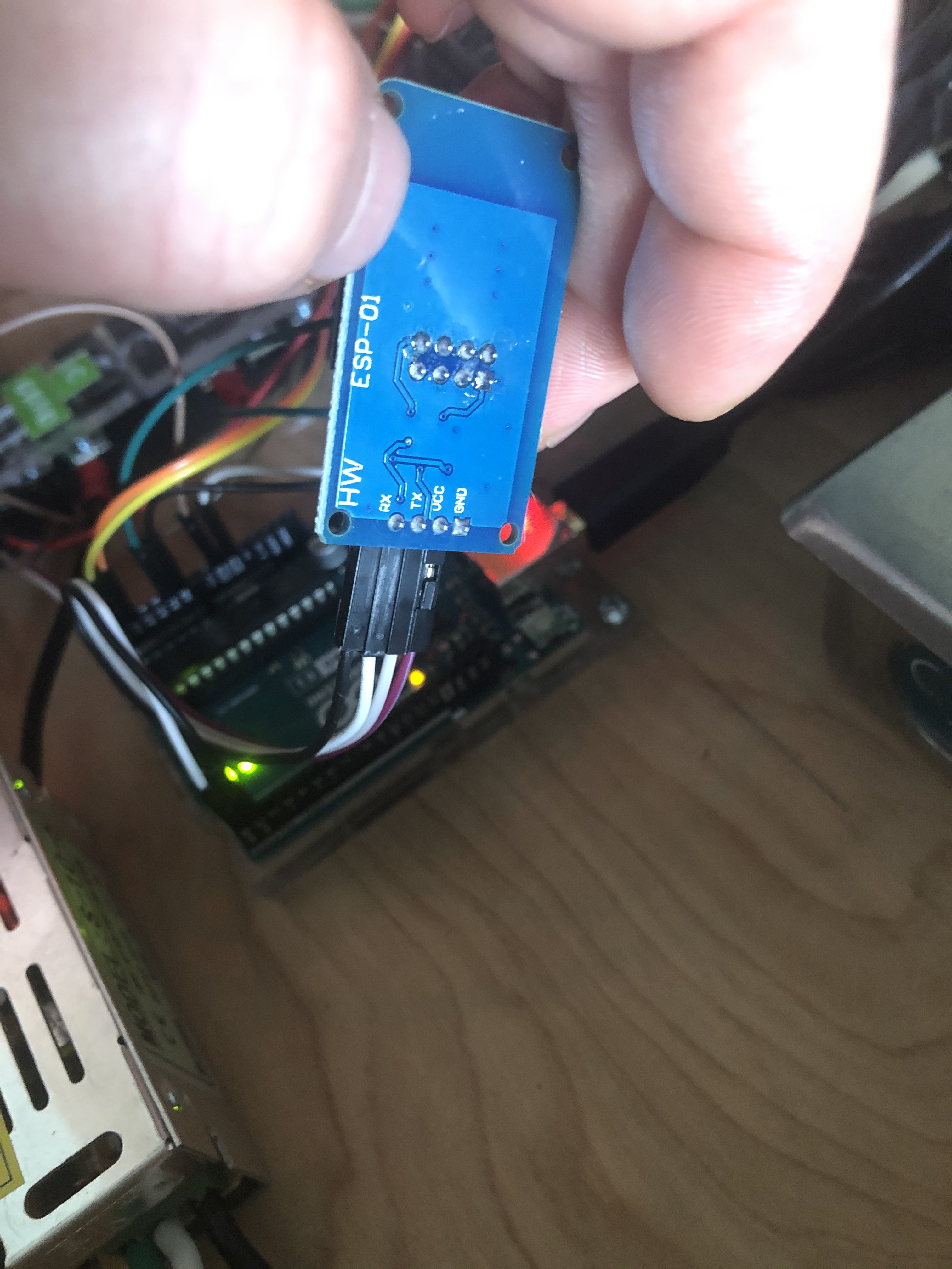
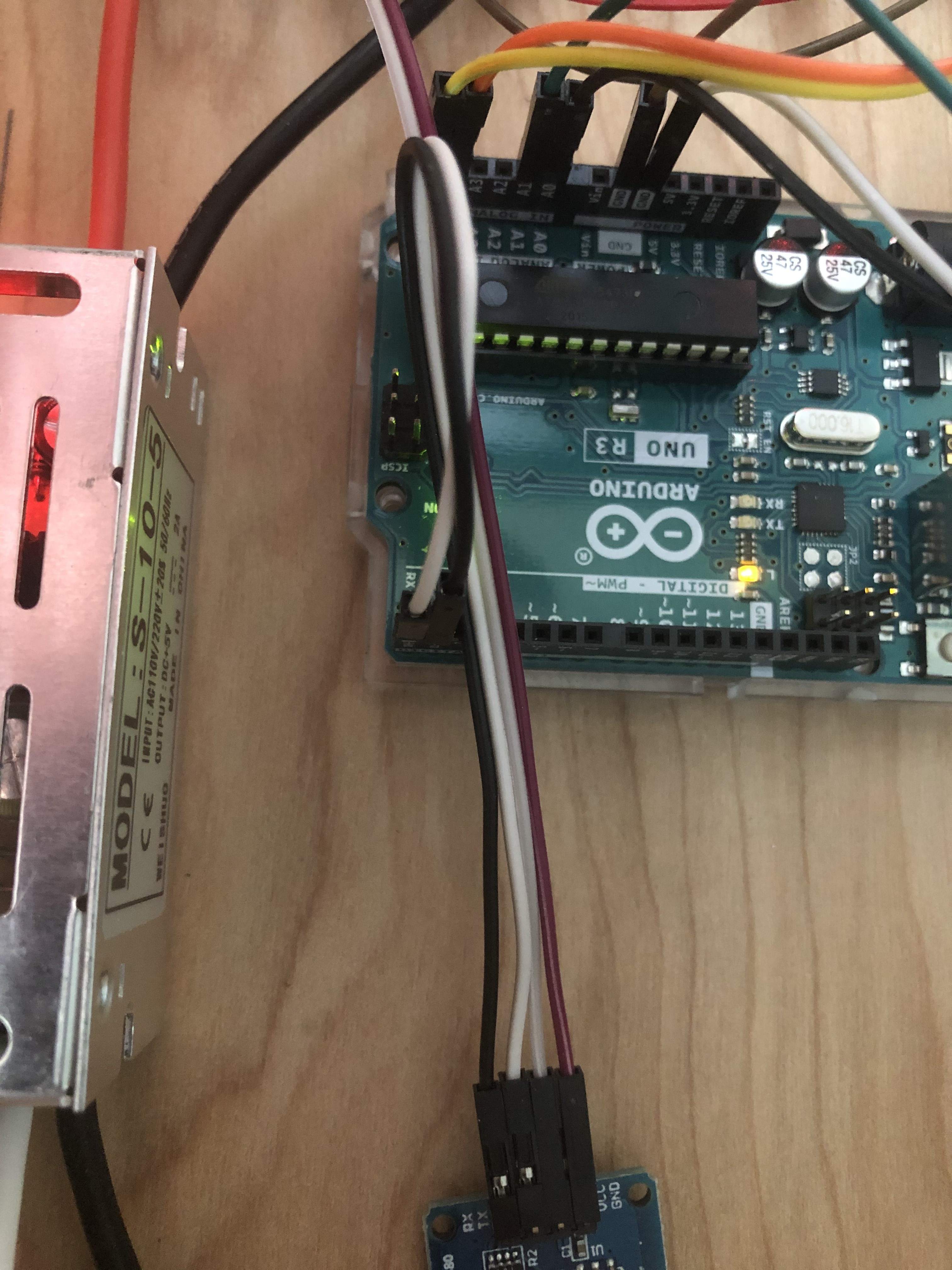
I’m working on a project where the goal is to be able to monitor and shut down (if necessary) a hot water boiler using a PT100 rtd, a pressure sensor, and a conductance type low water level cutoff. I have an Arduino Uno, an i2C lcd, and an ESP8266. Initially I got the code working to just display onto the physical lcd hardware. I also verified with some simple code that the ESP8266 is working correctly and able to communicate with the Blynk app. All devices are externally powered, and do not draw on the Arduino source.

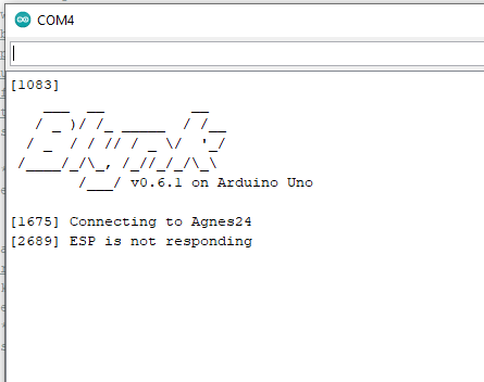
Next, I started integrating the code to work with Blynk so I can also monitor the values shown on the lcd on my phone as well. When I added the Blynk code, the lcd now stops showing anything, and continually reboots. Also, Blynk shows that the ESP8266 is continually going on and offline.

I looked all around the Blynk site and others to try to piece together a solution for this problem, but all examples appear to be just different enough to solve my specific problem. Also, I’m just learning how to code, so I’m learning as I go.

Any help in identifying where my code is problematic is greatly appreciated.

Thanks.

/*
  The following functions are included within this program
  
  Monitor P100 RTD
  Reads an analog input on pin 0, converts it to voltage, and prints the result to a LCD Screen.
  This example code is in the public domain.
  http://www.arduino.cc/en/Tutorial/ReadAnalogVoltage

  Monitor Pressure Transducer
  Uses a standard 3-wire pressure transducer and reads the analog signal, then converts the signal to a 
  readable output and displays it onto a LCD screen.

  Monitor Low Water
  Using a GuradDog RB-24E conductance type low water cut-off switch, the device is powered by the
  24V DC power supply. The 'pass-through' yellow leads of the device normally pass the 24V DC supply
  through to the boiler to power it when the sensor senses water. In this case, the leads will be 
  connected to a 24V DC to 5V DC step down regulator. The regulator will normally supply 5V DC to the 
  Arduino when the RB-24E senses water. When the RB-24E does not sense water, the 5V supply will stop
  supplying power to the Arduino. The Arduino will then signal a relay to interrupt the boiler
  power supply.

  Values are sent to Blynk App via ESP8266 WiFi Module
 */
#include <Wire.h> //includes outside library allowing communication over i2c devices
#include <LiquidCrystal_I2C.h> //includes outside library allowing interfacing with LCD screens
#include <math.h> //mathematical functions for manipulating floating-point numbers
#include <ESP8266_Lib.h> //ESP8266 interface library
#include <BlynkSimpleShieldEsp8266.h> //Blynk interface with ESP8266

//Blynk communication variables
#define ESP8266_Baud 115200 //constant to set baud rate for the ESP8266 module
#define BLYNK_PRINT Serial //redirects built-in status prints like ASCII logo and time stamped messages to serial monitor

//pressure measurement variables
float       pressureInput = A1; //select the proper analog input pin for the 3-wire pressure transducer
const float pressureZero = 99.5; //analog reading of pressure transducer at 0 psi
const float pressureMax = 929.775; //analog reading of pressure transducer at 150 psi
const int   pressureTransducerMaxPSI = 150; //maximum pressure rating of transducer being used.
float       pressureValue = 0; //variable to store the pressure value calculated from analog value 

//temperature measurement variables
float       tempInput = A0; // select the proper analog input pin for the P100 RTD
const int   tempMax = 1023; //analog reading of PT100 RTD at 572 deg F
const float tempVoltageMax = 5.0; //constant set to the maximum voltage reading of P100 RTD
const int   tempMaxDeg = 392; //constant set to the maximum temperature reading of the transmitter in deg F
const int   tempMinDeg = 0; //constant set to the minimum temperature reading of the transmitter in deg F
float       tempValue = 0; //variable to store the temperature value calculated from analog value
float       tempVoltage = 0; //variable to store the calculated voltage
float       round_tempValue = 0; //variable to store rounded tempValue

//GuardDog RB-24E monitoring Variables
int         voltageInput = A2; //select the proper analog input pin for 5V

//display variables
const int   baudRate = 9600; //constant to set the baud rate for the serial monitor
const int   sensorReadDelay = 1000; //constant integer to set the sensor read delay in milliseconds
const int   pressDisplayDelay = 500; //constant integer to set the pressure status message read delay in milliseconds
const int   tempDisplayDelay = 1500; //constant integer to set the temperature status message read delay in milliseconds
const int   lwcoDisplayDelay = 2500; //constant integer to set the low water cut-off status message read delay in milliseconds

//digital output to control relay
const int   digOutPin = 7; //Assigns the digital output pin beting used to actuate relay

//Blynk code to communicate with ESP8266 and Blynk app
char auth[] = ""; //auth code given by Blynk app
// Your WiFi credentials.
// Set password to "" for open networks.
char ssid[] = "";
char pass[] = "";
//use Software Serial on Uno, Nano...
#include <SoftwareSerial.h>
SoftwareSerial EspSerial(2, 3); // RX, TX
ESP8266 wifi(&Serial);

LiquidCrystal_I2C lcd(0x27, 20, 4); //sets the LCD I2C communication address: format(address, columns, rows)

BlynkTimer timer;

//function sends Arduino's up-time every second to Virtual Pin
//in app, Widget's reading frequency should be set to PUSH. This means that you define how often to send data to Blynk app

void myTimerEvent1() 
{
Blynk.virtualWrite(V5, pressureValue);
}

void myTimerEvent2()
{
Blynk.virtualWrite(V6, tempVoltage);
}

void myTimerEvent3()
{
Blynk.virtualWrite(V7, round_tempValue);
}

void myTimerEvent4()
{
Blynk.virtualWrite(V8, voltageInput);
}

//the setup routine runs once when reset is pressed:
void setup() 
{
Serial.begin(baudRate); //initializes serial communication at selected baud rate bits per second
delay(10);
lcd.init(); //initializes the LCD screen
lcd.init(); //initialized the LCD screen
lcd.backlight(); //initializes the LCD backlight

pinMode(digOutPin, OUTPUT); //the assigned pin will control the relay with an output
digitalWrite(digOutPin, HIGH); //relay will be activated interrupting power to boiler when pin is LOW

//Blynk code to communicate with ESP8266 and Blynk app
Serial.begin(ESP8266_Baud);
delay(10);
Blynk.begin(auth, wifi, ssid, pass);

//setup a function to be called every second
timer.setInterval(1000L, myTimerEvent1);
timer.setInterval(1000L, myTimerEvent2);
timer.setInterval(1000L, myTimerEvent3);
timer.setInterval(1000L, myTimerEvent4);

}

//the void loop routine runs over and over again forever:
void loop() 
{
  
//the following applies only to monitoring the pressure transducer
pressureValue = analogRead(pressureInput); //reads value from the input pin and assigns a variable
pressureValue = ((pressureValue - pressureZero) * pressureTransducerMaxPSI) / (pressureMax - pressureZero); // conversion equation to convert analog reading to psi
 
Serial.print(pressureValue, 1); //prints value from previous line to serial
lcd.setCursor(0,2); //sets cursor to column 0, row 2
lcd.print("Press.: "); //prints label
lcd.print(pressureValue, 1); //prints pressure value to LCD screen, 1 digit on float
lcd.print(" psig"); //prints label after value
lcd.print("   "); //to clear the display after large values or negatives
delay(sensorReadDelay); //delay in milliseconds between read values

//the following logic changes display and controls relay based on pressure conditions
if (pressureValue >= 28) {
digitalWrite(digOutPin, LOW); //activates relay, interrupting power to boiler
lcd.setCursor(0,3); 
lcd.print("Pressure Too High!! "); //prints label
delay(pressDisplayDelay);
} 
else if (pressureValue <= 10) { 
digitalWrite(digOutPin, LOW); //activates relay, interrupting power to boiler
lcd.setCursor(0,3);
lcd.print("Pressure Too Low!!  "); //prints label
delay(pressDisplayDelay);
} 
else {
lcd.setCursor(0,3);
lcd.print("System Press. Normal");
delay(pressDisplayDelay);
}
 
//the following applies only to monitoring the P100 RTD
tempValue = analogRead(tempInput); //reads value from the input pin and assigns a variable
tempVoltage = tempValue * (tempVoltageMax / tempMax); //calculated voltage
tempValue = (93.867 * ((tempValue * (tempVoltageMax / tempMax))) - 65.707) + 1.041; //converts the analog reading to deg F
round_tempValue = roundf(tempValue * 1000); //rounding to 3 decimal places
round_tempValue = round_tempValue / 1000;
  
Serial.print(tempValue, 1); //prints value from previous line to serial
lcd.setCursor(0,0); //sets cursor to column 0, row 0
lcd.print("Temp.:  "); //prints label
lcd.print(round_tempValue, 0); //prints temperature value to LCD screen, 0 digits on float
lcd.print(" "); //prints space after value
lcd.print((char)223); //prints degree symbol after space
lcd.print("F"); //prints F after degree symbol
lcd.print("   "); //to clear display after large values or negatives
delay(sensorReadDelay); //delay in milliseconds between read values

Serial.print(tempVoltage, 1); //prints value from voltage calculation to serial
lcd.setCursor(0,1); //sets cursor to column 0, row 1 
lcd.print("Temp.V.:"); //prints label
lcd.print(tempVoltage, 3); //prints voltage value to LCD screen, 3 digits on float
lcd.print(" volts"); //prints label after value
lcd.print("   "); //to clear display after large values or negatives
delay(sensorReadDelay); //delay in milliseconds between read values

//the following logic changes display and controls relay based on temperature conditions
if (tempValue >= 250) {
digitalWrite(digOutPin, LOW); //activates relay, interrupting power to boiler
lcd.setCursor(0,3); 
lcd.print("Temp. Too High!!   "); //prints label
delay(tempDisplayDelay);
} 
else if (tempValue <= 45) {
lcd.setCursor(0,3);
lcd.print("Temp. Too Low!!     "); //prints label
delay(tempDisplayDelay);
} 
else {
lcd.setCursor(0,3);
lcd.print("System Temp. Normal ");
delay(tempDisplayDelay);
}

//the following applies only to monitoring the GuardDog RB-24E
if (voltageInput <= 1000) {
digitalWrite(digOutPin, LOW); //activates relay, interrupting power to boiler
lcd.setCursor(0,3);
lcd.print("LowH2OLvl Detected!!"); //prints label
delay(lwcoDisplayDelay);
}
else {
lcd.setCursor(0,3);
lcd.print("Water Level OK      "); //prints label
delay(lwcoDisplayDelay);
}
  
//Blynk code to communicate with ESP8266 and Blynk app
Blynk.run(); //initiates Blynk
timer.run(); //initiates BlynkTimer
}

Your void loop is a mess!
Everything except the last two lines needs to be moved out, and called with a timer. You may be better-off going back to your original code to do this, then moving forward from there.

Read this…

Pete.

Thanks for the fast response. I’ll start over from the original un-blynked code now that I am getting a better idea of how things work.

Regards,
Jesse

Continuing the discussion from Integrating Blynk with Arduino Uno, ESP8266, and i2c Lcd:

Continuing from my first post (above)… I edited the code to try and at least get it working before adding the rest of the functionality shown in the initial post. I added a timer and got everything out of the void loop. I also changed the baud rate of the ESP8266 to 9600 using AT commands in case it was incompatible with Arduino Uno. I still can’t get the i2c lcd or Blynk to connect. Any additional advice in how to fix the code would be greatly appreciated.

Thanks,
Jesse


#define BLYNK_PRINT Serial
#include <ESP8266_Lib.h>
#include <BlynkSimpleShieldEsp8266.h>
#include <Wire.h> //includes outside library allowing communication over i2c devices
#include <LiquidCrystal_I2C.h> //includes outside library allowing interfacing with LCD screens

char auth[] = "Tcivy65XclOzyqZB9rdv1BeGgO58A-JW";
char ssid[] = "Agnes24";
char pass[] = "dresserrand";
#include <SoftwareSerial.h>

SoftwareSerial EspSerial(2, 3); // RX, TX

#define Esp8266_baudRate 9600
ESP8266 wifi(&EspSerial);

//pressure measurement variables
float       pressureInput = A1; //select the proper analog input pin for the 3-wire pressure transducer
const float pressureZero = 99.5; //analog reading of pressure transducer at 0 psi
const float pressureMax = 929.775; //analog reading of pressure transducer at 150 psi
const int   pressureTransducerMaxPSI = 150; //maximum pressure rating of transducer being used.
float       pressureValue = 0; //variable to store the pressure value calculated from analog value 

//display variables
const int   baudRate = 9600; //constant to set the baud rate for the serial monitor
const int   sensorReadDelay = 1000; //constant integer to set the sensor read delay in milliseconds
const int   pressDisplayDelay = 500; //constant integer to set the pressure status message read delay in milliseconds

LiquidCrystal_I2C lcd(0x27, 20, 4); //sets the LCD I2C communication address: format(address, columns, rows)

BlynkTimer timer;

void myTimerEvent()
{
 pressureValue = analogRead(pressureInput); //reads value from the input pin and assigns a variable
 pressureValue = ((pressureValue - pressureZero) * pressureTransducerMaxPSI) / (pressureMax - pressureZero); // conversion equation to convert analog reading to psi

Serial.print(pressureValue, 1); //prints value from previous line to serial
 lcd.setCursor(0,2); //sets cursor to column 0, row 2
 lcd.print("Press.: "); //prints label
 lcd.print(pressureValue, 1); //prints pressure value to LCD screen, 1 digit on float
 lcd.print(" psig"); //prints label after value
 lcd.print("   "); //to clear the display after large values or negatives
 delay(sensorReadDelay); //delay in milliseconds between read values

  Blynk.virtualWrite(V5, pressureValue);
}

void setup()
{
Serial.begin(baudRate); //initializes serial communication at selected baud rate bits per second

EspSerial.begin(Esp8266_baudRate);
delay(10);

lcd.init(); //initializes the LCD screen
lcd.backlight(); //initializes the LCD backlight

Blynk.begin(auth, wifi, ssid, pass);

timer.setInterval(1000L, myTimerEvent);

}
void loop()
{
 Blynk.run();
 timer.run(); //initiates BlynkTimer
} 

There’s no need to start a new topic, I’ve merged your new one into your old one.

Pete.

I’m unclear if you managed to get the LCD display working without adding Blynk or not.
If not, then have you used an I2C scanner to identify the display address on your I2C bus?

What does your serial monitor show with this code?

Pete.

I did get the LCD display working without the Blynk code, displaying all information that was included in the original code posted. With this code, the monitor will initiate, but will not show any information at all.

Pete.

The backlight works, but no information is shown at all.

I think you are referring to the LCD display. i’m Asking about your serial monitor within the Arduino IDE.

Pete.

Apologies… See attached.

I did get the setup to work without Blynk and without adding the LCD code.

image

An additional note…the serial monitor is at 9600 when this is shown…

Wiring problem?
Maybe you have Rx to Rx rather than Rx to Tx ?

Pete.

I double checked. They seem to be wired correct. I also used the adapter with another sketch to verify that it works, so I know that isn’t the problem. The ESP is powered by a separate 5V source.

Just to prove it to myself, I ran the other sketch (without Blynk or i2c lcd code included) to verify that the hardware and Blynk is working. It connected immediately at both 9600 and 115200 baud rates.

I’ve been doing some further troubleshooting of what my issue is. I found that, in the above code, instead of:

ESP8266 wifi(&EspSerial);

I use:

ESP8266 wifi(&serial):

and I change

EspSerial.begin(Esp8266_baudRate);

to:

Serial.begin(Esp8266_baudRate);

I can get the code to intermittently connect to the app. It will disconnect and reconnect every 10 seconds or so. The app still does not show any data, and the LCD still does not show anything.

Regards,

Jesse

I’ve been working on correcting and troubleshooting my code in an attempt to pinpoint what is causing my problem. I realize the last few pieces of code had some issues. The reduced, simplified code works:


#include <Wire.h> //includes outside library allowing communication over i2c devices
#include <LiquidCrystal_I2C.h> //includes outside library allowing interfacing with LCD screens

#define BLYNK_PRINT Serial
#include <ESP8266_Lib.h>
#include <BlynkSimpleShieldEsp8266.h>

//pressure measurement variables
float       pressureInput = A1; //select the proper analog input pin for the 3-wire pressure transducer
const float pressureZero = 99.5; //analog reading of pressure transducer at 0 psi
const float pressureMax = 929.775; //analog reading of pressure transducer at 150 psi
const int   pressureTransducerMaxPSI = 150; //maximum pressure rating of transducer being used.
float       pressureValue = 0; //variable to store the pressure value calculated from analog value 

//temperature measurement variables
//float       tempInput = A0; // select the proper analog input pin for the P100 RTD
//const int   tempMax = 1023; //analog reading of PT100 RTD at 572 deg F
//const float tempVoltageMax = 5.0; //constant set to the maximum voltage reading of P100 RTD
//const int   tempMaxDeg = 392; //constant set to the maximum temperature reading of the transmitter in deg F
//const int   tempMinDeg = 0; //constant set to the minimum temperature reading of the transmitter in deg F
//float       tempValue = 0; //variable to store the temperature value calculated from analog value
//float       tempVoltage = 0; //variable to store the calculated voltage
//float       round_tempValue = 0; //variable to store rounded tempValue

//GuardDog RB-24E monitoring Variables
//int         voltageInput = A2; //select the proper analog input pin for 5V

//display variables
const int   baudRate = 9600; //constant to set the baud rate for the serial monitor
//const int   sensorReadDelay = 1000; //constant integer to set the sensor read delay in milliseconds
//const int   pressDisplayDelay = 500; //constant integer to set the pressure status message read delay in milliseconds
//const int   tempDisplayDelay = 1500; //constant integer to set the temperature status message read delay in milliseconds
//const int   lwcoDisplayDelay = 2500; //constant integer to set the low water cut-off status message read delay in milliseconds

//digital output to control relay
//const int   digOutPin = 7; //Assigns the digital output pin beting used to actuate relay

char auth[] = "";
char ssid[] = "";
char pass[] = "";
#include <SoftwareSerial.h>

SoftwareSerial EspSerial(2, 3); // RX, TX
ESP8266 wifi(&Serial);

LiquidCrystal_I2C lcd(0x27, 20, 4); //sets the LCD I2C communication address: format(address, columns, rows)

BlynkTimer timer;

void myTimerEvent1()
{
Blynk.virtualWrite(V5, pressureValue);
}

void myTimerEvent2()
{
Blynk.virtualWrite(V6, millis() / 5000);
}

void myLCD()
{  
lcd.setCursor(0,0); //sets cursor to column 0, row 0
lcd.print("Press.: "); //prints label
lcd.print(pressureValue, 1);
//lcd.print(" psig"); //prints label after value
//lcd.print("   "); //to clear the display after large values or negatives
}

void setup()
{
Serial.begin(baudRate); //initializes serial communication at selected baud rate bits per second  
lcd.init(); //initializes the LCD screen
lcd.backlight(); //initializes the LCD backlight
lcd.setCursor(0,0);

EspSerial.begin(baudRate);
delay(10);

Blynk.begin(auth, wifi, ssid, pass);

timer.setInterval(1000L, myTimerEvent1);
timer.setInterval(1000L, myTimerEvent2);
timer.setInterval(1000L, myLCD);

}
void loop()

 {
 Blynk.run();
 timer.run(); //initiates BlynkTimer
 
//the following applies only to monitoring the pressure transducer
 pressureValue = analogRead(pressureInput); //reads value from the input pin and assigns a variable
 pressureValue = ((pressureValue - pressureZero) * pressureTransducerMaxPSI) / (pressureMax - pressureZero); // conversion equation to convert analog reading to psi
 
//the following logic changes display and controls relay based on pressure conditions
//  if (pressureValue >= 28) {
//  digitalWrite(digOutPin, LOW); //activates relay, interrupting power to boiler
 // lcd.setCursor(0,3); 
 // lcd.print("Pressure Too High!! "); //prints label
 // delay(pressDisplayDelay);
 // } 
 // else if (pressureValue <= 10) { 
 // digitalWrite(digOutPin, LOW); //activates relay, interrupting power to boiler
 // lcd.setCursor(0,3);
 // lcd.print("Pressure Too Low!!  "); //prints label
  //delay(pressDisplayDelay);
 // } 
 // else {
 // lcd.setCursor(0,3);
  //lcd.print("System Press. Normal");
//  delay(pressDisplayDelay);

 }

However, when I add the additional lines of text within the void myLCD() loop, Blynk will not connect:

void myLCD()
{  
lcd.setCursor(0,0); //sets cursor to column 0, row 0
lcd.print("Press.: "); //prints label
lcd.print(pressureValue, 1);
lcd.print(" psig"); //prints label after value
lcd.print("   "); //to clear the display after large values or negatives
}

I’m trying to figure out if something is wrong with my code, or if it is a problem with running out of Uno’s internal memory. Does anyone have any ideas?

Thanks,

Jesse

Following up on this in case it can help someone else in the same type of situation… I purchased a Mega clone and, minus code issues, this solved the problem I was having with Blynk continuously connecting and disconnecting every 5 - 8 seconds. As I suspected, the program was too large for the Uno to handle.

An important thing I need to do with my program is have it be able to run my program and update the LCD even when disconnected from the internet. Looking through the Blynk Community archives, I found the following code:


bool connectBlynk()
{ 
  if (Blynk.connectWiFi(ssid, pass))
    Serial.println("\nWiFi connected. Try Blynk");

  int i = 0;
  while ((i++ < 20) && !Blynk.connect()) 
  {
    BlynkDelay(500);
  }
  
  return Blynk.connected();
}

void loop()
{
    if (Blynk.connected())
    {
      Blynk.run();
    }
    else
    {
      Serial.println("No Blynk connection. Trying to connect");  
      connectBlynk();
    }

    timer.run();
}

of which I implemented in my program and works fine, continuously re-connecting with WiFi when it drops out and then becomes available again. If I want my program to run as it tries to re-connect with Blynk, should I basically copy the entire program and paste it inside the else condition in the void loop?

I tried doing this, and it kind of works, but makes everything lag pretty much to a standstill. I’m clearly not interpreting how to use the code properly, and need some help understanding how to proceed.

Thanks again,
Jesse

Blynk.connect blocks code execution while its trying to connect, but it then times-out if it can’t connect and program execution can continue.

Your code keeps repeating this attempt/timeout process, with a blocking delay thrown in there for good measure.

What I tend to do is attempt to connect then if it fails run in ‘offline’ mode. I’ll then attempt to re-connect and keep track of how may times I try and fail. If I fail too many times then I’ll increase the time between reconnection attempts.

Pete.

That explains why I’m seeing what I’m seeing. I don’t want anyone to write my code for me, but are there any good archives that might show a similar enough example of how this can be done effectively? I haven’t been able to find any, but it seems like doing this type of thing would have been something that would have come up before in this community.

Jesse