HERE is a github link to my existing project that’s been running for a little more than a year. I have a function on line 403 that I will paste below that listens for activity in my app from a button (V6), collects a multiplier value from a Step V (V5) and applies it to 1 of 8 digital pins assigned via Menu widget (V4). Currently the menu widget represents 8 digital pins on an Arduino Mega. Well I’m in the process of splitting this sketch up into segments according to functionality and migrating it all over to several ESP8266 boards, and because the ESP has way less pins, I find I’ll need to split this function up to be performed by 2 ESPs. That said, I would like to know if I can keep the app set up the same way it is now, except I’d like to assign the first 4 pins to ESP-A and the second 4 pins to ESP-B, and depending upon which of the positions of the Menu widget is selected will determine which board is selected in the Device Selector widget? I’m confident I’d be able to arrange this in code, but I am unable to find more information about this widget. I added this widget to a side project just to view the settings, but it won’t allow me to expand the amount of boards I’ll assign to it for reasons currently unknown, but before I get too deep into researching this widget, I’m asking for insight into whether it would be a viable option in that situation in the first place? In the past, I’ve inquired whether or not I can assign several AUTH keys to report to the same app, but Gunner set me straight on that topic, and this is just a followup to that as I still seek to achieve the same end result.
Here’s the function I’ll need to divide, but also know, I plan to add additional positions, so knowing the best approach will help me twice.
void dosingPumps()
{
  if (button == 1 && pumpRunning == false)
  {
    multiplier[x] = calibration;                      // Gets the value in [x] position from Blynk
    Blynk.virtualWrite(V4, 0);
    Blynk.virtualWrite(V5, 0);
    Blynk.virtualWrite(V6, 0);                        // Keeps button ON until fully executed
    pumpRunning = true;
    digitalWrite(pumpPin[x], HIGH);
    Blynk.virtualWrite(dosingLEDs[x], 255);           // [x] position Blynk indicator LED
    startPump = millis();
    runCount = DOSEml * multiplier[x];
    terminal.print("Dosing in: ");
    terminal.print(DOSEml);
    terminal.print(" milliliters of ");
    terminal.println(nuteType[x]);
  }
  if (millis() - startPump > runCount)
  {
    digitalWrite(pumpPin[x], LOW);
    Blynk.virtualWrite(dosingLEDs[x], 0);
    pumpRunning = false;
    button = 0;
  }
  terminal.flush();
}
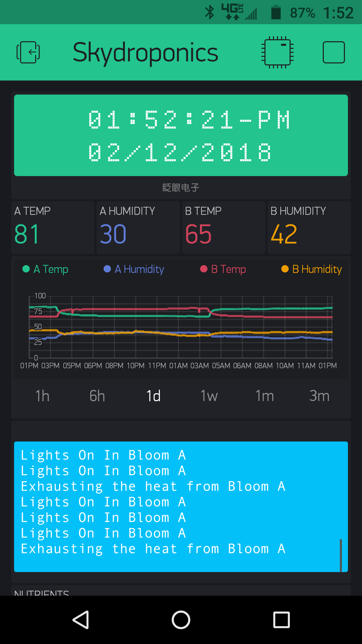
Edit - I also would like to know more about Tiles and if anyone thinks this widget might be applicable to my project. FYI, my project is a hydroponics controller. @Fettkeewl helped me last year put the above function together and get it working properly, but the project also monitors 2 DHT22s, an 8 channel relay, a physical RTC that is updated from Blynk cloud every minute and the relays are programmed to trigger by time, atmospheric values and also via Blynk as overrides and also one of the relays connects to a water pump that powers in in increments of time to produce 1 gallon (multiples and divisions of).
Sorry, but I am not quite following your need… But as I understand them, Device Selector and Device Tiles both allow multiple devices in one Project… each device would have it’s own AUTH and you could then select pins and actions, per device, as required.
I want to know if I can control the Device Selector with code. So if I choose options 1-4 of the Menu widget, it chooses Device-A and if I choose options 5-8 of the Menu widget, it chooses Device-B.
But as I see them, the Menu Widget is a way of selecting different device coded options (functions, timers, loops, logic, etc), whereas Device Selector and Tiles seem more for App driven control of vPins (AKA less device based code).
I rarely use App driven, non-script coded options… so I am not the best one to assist, but I was curious on the issue clarification.
When you look at the widgets (especially the menu) from the code, it’s a zero indexed array of positions, and with that I know I can further define those positions into groups with booleans. What I’m having difficulty with is the functionality of the Device Selector because when I added it to my app and opened its settings, I didn’t see any area for Vpins or even other device positions, but I think if those positions are also zero indexed (or similar), I can code rules with booleans that result in if any of Menu positions 0-3 are true, groupA = true. If groupA == true, select deviceA etc. So I don’t know if my widget isn’t set up correctly or what have you, but if it’s worth pursuing this further, I’ll debug that and begin splitting the above function into 2 groups. If not, I’ll have to keep digging for a more applicable method, maybe Tiles? Either case, I don’t see any images for those widgets in the docs section, so now I’m just spit balling and hoping for the best.
Nice to see you again, I’ve wondered what happened to you
How to Device Selector: In project settings > devices
Add several devices (MCUs, A…B…C)
They get their own auth codes
In device selector
You will now be able to see previously created devices for the project. This widget allows
you to set one as active
For every widget controlled by device selector
You should now be able to select a device source for that widget within that project
You either set a static source (Device A, B or C) or the last option “Device Selector”
Widget with device selector as source
Will now react to and from the selected device according to device selector
Scenario:
Create project
Create device A & B of similar function
Uppload same code with different Auth tokens to device A & B
Create device selector
Create button, assign device selector as source, hit play.
How to Device tiles: In project settings > devices
Add several devices (MCUs, A…B…C)
They get their own auth codes
Create device tiles and configure template
Hit the cogwheel, there you create a template which is to be shown ON the device tile itself, some text and a value, this is your “overview” of similar devices. You also assign what devices to use that template amongst other settings.
If you back out from the cogwheel you can “enter” your template and define how it will look like in terms of widgets. Theese widgets will be bound to selected devices, which devices you access is selected via the “overview”
Note that there are some bugs and quirks still in play with regards to widget behaviour when using device tiles/selectors. 1 crucial for me is that history is not retained in terminal widget
I would strongly advice against such a solution, if the lack of pins is an issue I suggest you turn to a I/O expander like the PCF8574. It’s controlled via i2c and gives you 8 I/O ports for the price of 2 on your device. (2 communication lines, power and gnd, 4 wires in total)
Thanks for all the feedback @Fettkeewl! It now dawned on me after reading your replies that I wouldn’t be able to code for the Selector widget due to there being independent sketches and CPUs, plus also the widget itself functioning the way it does and needing to be manually selected.
As to your suggestion to use the expander, may I ask your reasoning? Why I ask is because I now have a 3D printer and have designed and printed my own custom cases, each to hold 4 motors. I’ve also had to change the driver circuits (2x - L298N motor/stepper drivers) to account for the 3v3 logic and I’d really prefer not to need to redesign and reprint it all if at all possible. I am also intending to increase the pump count from 8 to 12 which would require another ESP at least, but if there’s a concern, I would like to know what it is as I will also be driving an 8 channel relay module, still using the RTC, the 2 DHT sensors and that’s just my current setup which I do intend to expand substantially. All in all, I estimate I’ll be needing to juggle up to 10 ESPs when I finish building my project the way I want.
Tbh I do not know enough of your project to tell wether or not you can/should divide it into multiple MCU’s
But, thinking of your current scenario, that you have only 1 mcu atm controlling it all and it works… going to multiples would requiere (depending on needed functionality)
Syncing between multiple devices
If dependent on eachother, failsafes when one MCU breaks
Tasksyncing
etc etc
But ofc its your project And you know it best I myself would never attempt a “split” of a project to increase I/O pins and coordinate multiple MCU’s to have them work together, it was once 1 project so everything is tied together I would presume
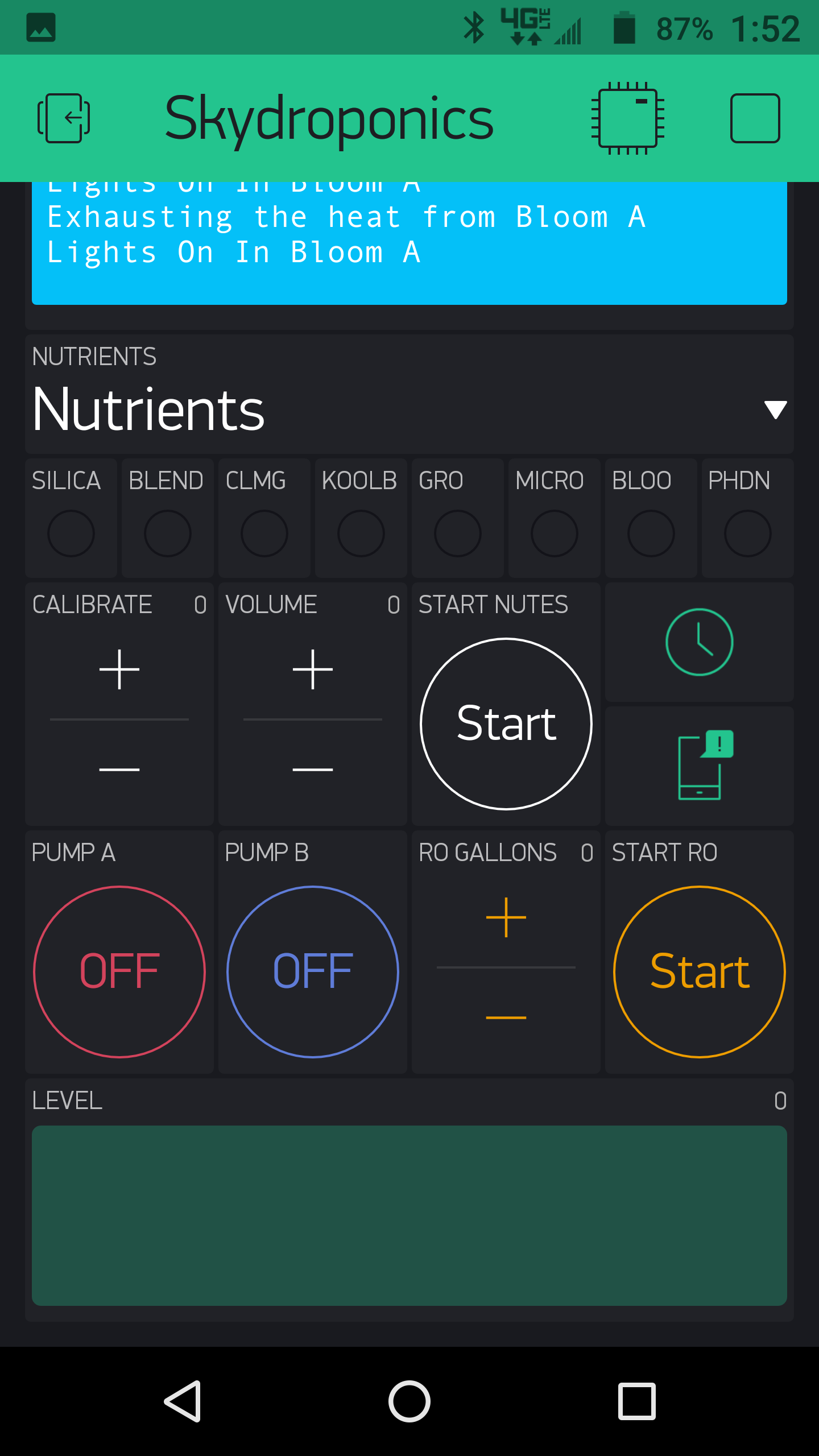
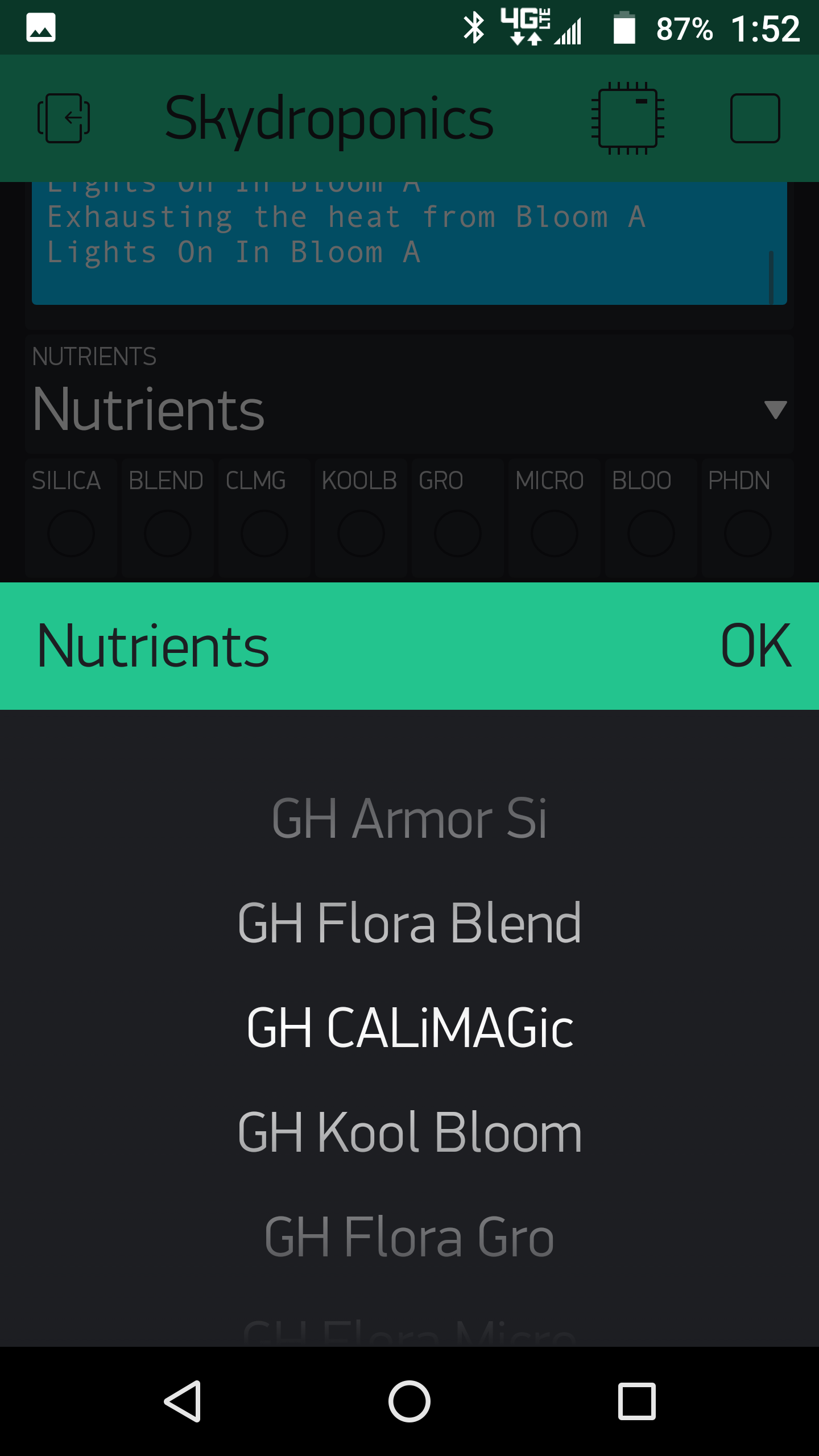
The entirety of my project will be a fully automated hydroponics controller consists of 2 bloom rooms and uses reverse osmosis water. I use about 10 different nutrient/supplements, 8 of which you helped me build code for the dosing system last year. So my project last year consisted of the 8 head peristaltic dosing system, 8 relays, an in circuit RTC and 2 - DHT sensors. HERE is the sketch for all of that. I quickly ran into problems when dosing water in gallons and nutrients in ml, while also doing all of the other functions at the same time and still talking to Blynk, my EtherMega’s (buffer?) quickly became over burdened t=and the MCU locked all pins in their current state when the crash occurred so devices stayed on or off until I discovered the crashed state and had to reset. I’ve since discontinued the pumps that you helped me code and still was able to produce a crash state with the decreased functionality. A seasoned coder has been working with me to improve my sketch to its current state (linked), but the reality is that the Atmega simply cannot keep up. I also intend on expanding my project by almost double. I also plan to add in nutrient monitoring with 2-3 probes (sensors) as well as save into memory the nutrient schedule for the brand that I use. There’s no way on earth I’d be able to fit all of that into a Mega, even with port expansion. My coder friend suggested various ideas from rPi to ESPs. Myself being a coding novice opted to go with ESPs to stick with the language I’m most comfortable with. All of that said, I realize this project is about to get a whole lot more complex, but I truly believe that it is inevitable.
ESP32, while still in a relative growth concerning it’s Arduino core, does work with Blynk and has more available and customisable pins then a typical ESP8266.
Since their cost is relatively low… not a mistake, just a learning curve. And it is not like you couldn’t use both or find other uses for anything unused in this project
Skybound, I am new to Blynk but have some experience with the issue you are encountering.
There are many reasons to prefer the approach of having several 4 port dosing controllers vs. a single 8, 12 or 16 port controller.
Some reasons that immediately occur to me are:
Scalability. Need more pumps? Add another 4 port controller.
Have a failure? Keep a spare 4 port device with pumps attached for quick changeout. It is both more difficult and potentially economically prohibitive to replace the 12 port controller if something fails.
When you have several wires per port, it becomes more and more difficult to physically get the wires into a small board even if it does have 30 more I/O pins. At some point you begin to knock wires loose as fast as you connect them. This doesn’t happen when you modularize.
The downside of such nearly identical modules (aside from MAC address) is that they need a manager process to support a single point of communication with the outside world (Blynk).
This is a significant issue since you need to have a protocol to communicate between all the modules and a manager, whether that manager is a separate dedicated device or one of the modules that runs the management function in addition to its doser pump control activity. The manager is the only one that would communicate with Blynk, collecting and dispersing the Blynk virtual pin data from and to the other modules.
I used this strategy to build a 32 bit EL wire controller from 4 8-bit controllers with low end AVR processors (Sparkfun), connecting them with the SPI bus.
With an ESP8266 you could also use the SPI capability or a mesh strategy based on WiFi to accomplish the same thing.
This is a pretty challenging task, however. It would be worthwhile if you are contemplating commercializing your design or convincing many people to use you work.
If you intend this to be for your sole use, the balance is probably in favor of the multi-IO (ESP32) board because, even though it has disadvantages, you can do the simple thing in the software, just adding more virtual pin handlers and associated ‘operational’ code.
My inspection of the functions available in the Blynk environment has not suggested any way to serve separate modules in a single project where it is necessary to act on them specifically. (The SuperChart can aggregate among several devices but the operations are all unordered – average, sum, median, min, max – using a common tag mechanism. That tag mechanism means that it cannot be easily extended to the retrieval of an array of values with known order, for example.)
Initially, I’ll be using Blynk to interact with each pump till I can be assured each operates with in my tolerable range of accuracy. After that, the pumps will be programmed in code and everything will be automated according to presets and at that stage, as it relates to my pumps, Blynk will be down graded to an observatory capacity.