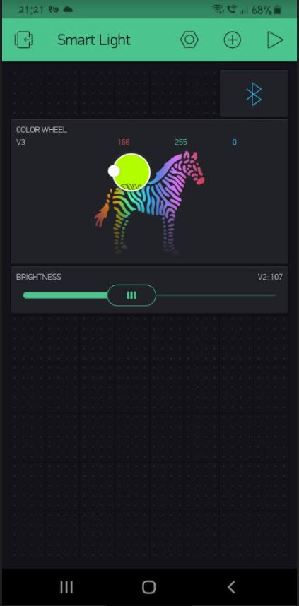
Hi, I am trying to control Ws2812B led strip with arduino. I have connected IFTTT with blynk but it only updates the RGB values to blynk application and there is no change in light color… HELP please!!!
@Costas
This is the software version of saying “my car won’t start, tell me what is wrong”. If you seriously expect someone to be able to help based on this information then you are seriously over estimating the psychic powers of the forum members.
When you created this topic you were asked to provide lots of helpful information about your hardware and software setup. This is the minimum that would be required, and in this case we would also need to have details of the IFTTT recipe too, and information about the widgets set-up in your Blynk app.
BTW, @Costas hasn’t visited this site for over 18 months.
Pete.
I have been using Arduino UNO along with Bluetooth module HC-06 and the light I’m using is WS2812b.
I’m using the Blynk app as a controller for the light. I have linked Blynk with IFTTT and when I ask google assistant to turn on the light it has to set RGB value to 255 each. It does perform the activity to Blynk application but there is no change in light.
code used in Arduino:
{
  Serial.begin(9600); //begins the serial communication.
  Blynk.begin(Serial,auth);
  FastLED.addLeds<LED_TYPE, PIN1, COLOR_ORDER>(leds1, NUM_LEDS1).setCorrection( TypicalLEDStrip );
}


BLYNK_WRITE(V3)
{
  r=param[0].asInt();
  g = param[1].asInt();
  b = param[2].asInt();

  static1(r,g,b,data);
}

BLYNK_WRITE(V2)
{
  data=param.asInt();

  static1(r,g,b,data);
}


void loop()
{
  Blynk.run();

}
void static1(int r, int g, int b, int brightness)
{
 FastLED.setBrightness(brightness);
 for (int i = 0; i < NUM_LEDS1; i++ )
 {
  leds1[i] = CRGB(r,g,b);
 }
 FastLED.show();
}
blynk app pins config:
and the buttons send values when released… @PeteKnight
@Sudan please edit your post, using the pencil icon at the bottom, and add triple backticks at the beginning and end of your code so that it displays correctly.
Triple backticks look like this:
```
Pete.
You appear to be missing quite a large part of your sketch, and any details of your IFTTT setup.
Pete.
trigger is : “light on”
makes request using webhooks
connection to Blynk:
http://45.55.96.146/auth token of blynk/pin/V3
method : PUT
content type : application/json
body : [“255”,“255”,“255”]
@PeteKnight
Try posting your full code.
Pete.
#define BLYNK_PRINT Serial

#include <SoftwareSerial.h>
SoftwareSerial DebugSerial(0, 1); // RX, TX

//#define BLYNK_PRINT DebugSerial

#include <BlynkSimpleSerialBLE.h> // including library.

#include "FastLED.h" // including library.

#define NUM_LEDS1 10// defining number of bulbs in the led strip.

#define LED_TYPE    WS2812 // type of led strip.

#define COLOR_ORDER GRB

CRGB leds1[NUM_LEDS1];

char auth[] = "1dYf0tD0aMC2xsj4KLsgDoAyik5s5Y5L"; // authentication token of blynk app stored in auth array.

#define PIN1 6

int data=0;
int r,g,b;


BLYNK_WRITE(V3)
{
  r=param[0].asInt();
  g = param[1].asInt();
  b = param[2].asInt();

  static1(r,g,b,data);
}

BLYNK_WRITE(V2)
{
  data=param.asInt();

  static1(r,g,b,data);
}

void setup()
{
  Serial.begin(9600); //begins the serial communication.

  Blynk.begin(Serial,auth);
  FastLED.addLeds<LED_TYPE, PIN1, COLOR_ORDER>(leds1, NUM_LEDS1).setCorrection( TypicalLEDStrip );

}

void loop()
{
  Blynk.run();
}

void static1(int r, int g, int b,int brightness)
{
 FastLED.setBrightness(brightness);
 for (int i = 0; i < NUM_LEDS1; i++ )
 {
  leds1[i] = CRGB(r,g,b);
 }
  FastLED.show();
}
Okay, I don’t use Bluetooth as a connection method for my devices, and although I know that there are some restrictions in the way that Blynk works over Bluetooth compared to an Ethernet/WiFi connection, I’m not really certain what these are.
Obviously, your phone will need to have the Bluetooth connection to the Arduino established before any commands can reach the Arduino, whether these are directly from the phone or via IFTTT.
The comments that I will make regarding your code are…
-
Setting the RGB to 255,255,255 won’t turn it on as such, it will simply set it to white. The On/Off function comes from the brightness command, so it depends what brightness the strip has been set to in your phone, using the slider connected to pin V2.
I’d probably add aBlynk.syncVirtual(V2)command to theBLYNK_WRITE(V3)callback before the line that saysstatic1(r,g,b,data)so that thedata(brightness) variable is populated with the current slider setting. Obviously, if the slider is at 0 then the lights will come on at zero brightness. -
You are creating a SoftwareSerial port called
DebugSerialon pins 0 and 1 (the Rx and Tx pins that your HC-06 are connected to). You can’t share the single hardware serial port pins in this way. The whole idea of creating a SoftwareSerial port is to allow you to use different pins for your debug messages. However, you’d need an FTDI adapter for this, which I guess you don’t have, and you’d need to direct Blynk’s built-in serial output to the debug port using#define BLYNK_PRINT DebugSerial
I’d suggest you remove the following lines from your code to prevent these serial port conflicts…
#define BLYNK_PRINT Serial
#include <SoftwareSerial.h>
SoftwareSerial DebugSerial(0, 1); // RX, TX
You’d actually be far better using something like a NodeMCU as your board for this project, and controlling it via WiFi, as then the lights could be controlled via Google Assistant/IFTTT at any time, not only when your phone is in the same area and paired with the Bluetooth module.
Pete.
