Hello,
i just started in blynk and im working on lighting a real led using one button widget and closing it with the other using a NodeMCU.
I know its too easy, im just a starter in blynk and so i progress until i can do advanced projects .
Anyways i want to know how to use the BLYNK_READ in the if statement,
it would be nice if you answered!
Here is the code(just in case anyone needed to see it):
#define BLYNK_PRINT Serial


#include <ESP8266WiFi.h>
#include <BlynkSimpleEsp8266.h>
char auth[] = "private";
char ssid[] = "HUAWEI-E5172-6065";
char pass[] = "private";
#define LED 1
BlynkTimer timer;

void myTimerEvent()
//i want the if statement to be here

void setup()
{
  // Debug console
  Serial.begin(9600);

  Blynk.begin(auth, ssid, pass);
  // You can also specify server:
  //Blynk.begin(auth, ssid, pass, "blynk-cloud.com", 80);
  //Blynk.begin(auth, ssid, pass, IPAddress(192,168,1,100), 8080);
pinMode(LED,OUTPUT);
  // Setup a function to be called every second
  timer.setInterval(1000L, myTimerEvent);
}

void loop()
{
  Blynk.run();
  timer.run(); // Initiates BlynkTimer
}
Turning a physical LED On/Off using a button widget is more easily achieved using a single button widget rather than two. This is how to do it…
Add a button widget to your app, set it to Switch mode, and attach it to Virtual Pin V10
Then add this code to your sketch…
BLYNK_WRITE(V10)
{
  if (param.asInt()) // If the button widget sent a "1" (on)
  {
      digitalWrite(LED, 1); // Turn your LED on
  }
  else
  {
      digitalWrite(LED, 0); // Turn your LED off
  }
}
The BLYNK_WRITE(V10) callback is automatically triggered each time the value of the widget attached to V10 changes in the app.
If you want to use two widget buttons then it gets a bit more complex, so probably isn’t the best solution for a beginner.
Hello,
it didnt work!!!
i dont know what on earth is going on but im sure its a mistake i didnt see.
Sorry Pete for all that anger but im really just going to explode of anger,
here is the new code:
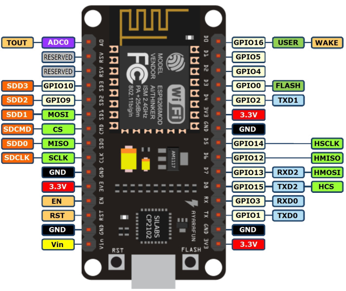
This isn’t a great pin to use, because if GPIO0 is pulled HIGH at startup then it will put your NodeMCU into programming mode rather than executing your sketch. See this for more info…
It may be simpler to work with the built-in Blue LED that is located near the D0 pin. This is connected to GPIO2, so change your code like this:
#define red 2
The built-in LED has inverted logic, so HIGH will turn it off, and LOW will turn it on.
Swapping the HIGHs and LOWs in your digitalWrite commands will fix this.
 .
.