Hydroponics code and supply

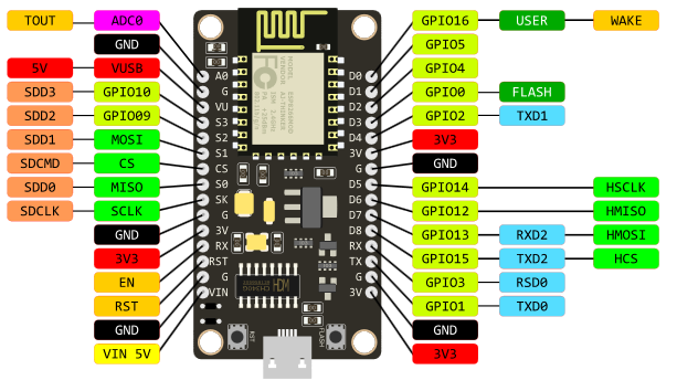
Hi! We’re currently working with a project entitled Hydroponics: Water Level Monitoring and Irrigation. When the hc-sr04 sensed that the water level is low, it will send a notification in blynk and automatically open the water pump. I’m using NodeMCU, 6V-9V water pump, 5V 1ch relay. We already have a code but is not tested yet. We’re having a debate whether to connect
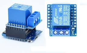
(a.) a 3V supply to the nodemcu, 5V supply to the relay and another 6V supply to the water pump or (b.) do we just supply the 3V in nodemcu, and 5V in relay? We are afraid that we might damage the nodemcu. We connect a 2N2222 transistor and 4.7kohm resistor in the relay.

And if possible, we would really appreciate it if you check our code. We already compiled it in Arduino IDE and it has no error, but we are still hesitant if it will really work.

//Define Pin Numbers
const int trigPin = D1;
const int echoPin = D2;
const int PumpPin = D5;  //relay --OUTPUT


//Define Variables
long duration;
int distance;

#include <ESP8266WiFi.h>
#include <Blynk.h>
#include <BlynkSimpleEsp8266.h>

//WiFi Connection//
char auth [] ="   ";
char ssid [] ="   ";
char pass [] ="   ";

//TIMER//
BlynkTimer timer;


//BLYNK//
//PINV2 IS LEVEL V WHICH MEASURES DISTANCE


void MeasureCm()
{
  //clears the trigPin
digitalWrite(trigPin,LOW);
delayMicroseconds(2);

  //sets the trigPin on HIGH state for 10 microseconds
digitalWrite (trigPin,HIGH);
delayMicroseconds(10);
digitalWrite(trigPin,LOW);

  //Calculating the distance and volume
distance=duration*0.034/2;
  {
if(distance>=10)
    {
Blynk.notify("Water is low. Water Pump On."); //notifies the Blynk user when the water level is low
digitalWrite(PumpPin, LOW); // To be used with Relay module (inverted logic: activate with LOW)
    }
else
    {
if(distance<10)
      {
Blynk.notify("Water is high. Water Pump Off.");  //notifies the Blynk user when the water level is high
digitalWrite(PumpPin, HIGH); // To be used with Relay module (inverted logic)
      }
    }
  }
}

void sendData()
{
  //SEND DATA TO BLYNK
Blynk.virtualWrite(V2,distance); //virtual pin 2 in Blynk -- Level V
}


void setup() 
{
Serial.begin(9600);
Blynk.begin(auth,ssid,pass);

pinMode(trigPin,OUTPUT);
pinMode(echoPin,INPUT);
pinMode(PumpPin,OUTPUT);
digitalWrite(PumpPin,HIGH);      // To be used with Relay module (inverted logic: normally HIGH)


timer.setInterval(5000,sendData);

}

void loop() 
{
timer.run();  //initiates SimpleTimer
Blynk.run();  //initiates Blynk
}


I’d use common ground on the 3 and 5 V supply. Not sure how the transistor would behave otherwise. If the pump works with 5 V I wouldn’t bother getting a third power supply.

How will you power the pump then? :stuck_out_tongue_winking_eye:

Depending on the specifications on your MCU, you might be able to power it from 5 V (BUT DON’T DO IT BEFORE CHECKING THE SPECS). As long as you connect the right voltage to the right pin, you don’t fry the NodeMCU.

Quick glance at your code: You never run the MeasureCm() function?!

Only one way to find out!! :sunglasses:

Also, if you search the forum you’ll find many projects about irrigation and relays.

I think MeasureCm() is typically invoked corresponding to a timer interval,

timer.setInterval(1000, MeasureCm);

I’d suggest that you use a relay board that is designed for use with a NodeMCU - one that has proper opto-isolation. That way, you won’t need the external components and you’ll be certain that there wont be any back-EMF problems affecting your NodeMCU.

The NodeMCU can be powered by 3.3v or 5v, provided that voltage is applied to the correct pins. When you plug the NodeMCU into a PC, it’s receiving 5v via the USB connector. The onboard voltage regulator steps thus down to 3.3v
Exactly the same thing happens when you apply 5v to the pin in the Vin pin (in the bottom left hand corner of this diagram):

image

There’s no reason why the same 5v supply can’t be used to power both the NodeMCU and the relay board. However, the PSU needs to be able to deliver sufficient current so that there is no dip in supply voltage when the relay operates. If you find that the NodeMCU reboots or disconnects from Wi-Fi when the relay coil is energised then you may be seeing ‘brownouts’ in the supply voltage because the PCU is under-rated in terms of its current output.

As far as the supply that is being switched is concerned, it should be independent of the supply for the NodeMCU and relay. You’d obviously take that approach if the relay was switching mains voltages, so treat the supply for the pump in the same way.

If you’re looking for a more compact solution than a NodeMCU and relay board the you could consider using the Wemos D1 Mini, plus a relay shield.
The D1 Mini is the same as a NodeMCU, it just has fewer pins available, to allow it to be packaged on a smaller board. The Wemos relay shield used pin D1 (GPIO5) to activate the relay, and it’s configured to be active HIGH, which means the relay actuates when a logic HIGH signal is applied to GPIO5.

The relay shield can be stacked on top of the D1 Mini like this:
image

Or side by side if one of these dual bases is used:
image

Comments about your code…
It’s good programming practice to refer to pins by their GPIO pin number, rather than the “D” number that’s printed on the NodeMCU/Wemos boards. This allows greater portability of code between types of devices. There’s nothing stopping you adding the corresponding “D” number as a comment alongside the pin definition to help with wiring.

As @wickedbeernut said, you need to call your MeasureCm() with a timer. You could get the MeasureCm() function to call the sendData() once a reading has been taken, rather than calling sendData() with a timer.

I think you may have some problems when the water level is around the 10cm level. Your distance variable is an integer, which will give you some smoothing, so at around the 10cm level the value will be 9, 10 or 11 but you may find that you’re getting unwanted on/off switching of the pump and unwanted notifications when the level us hovering around the 10cm mark. You could change this by giving a broader range of allowable values before the pump kicks-in or switches off.

Pete.

Should we just write “timer.setInterval(1000,MeasureCm);”? Then just put the sendData inside the void MeasureCm?

You could change ge your ‘if’ statement so that instead of working on =10 and >=10 you could wait until the level drops to say 12 before starting the pump.

Pete.

I’ll give you a clue, it’s to do with the code in this area:

if(distance>=10)
  {
    Blynk.notify("Water is low. Water Pump On."); //notifies the Blynk user when the water level is low
    digitalWrite(PumpPin, LOW); // To be used with Relay module (inverted logic: activate with LOW)
  }
else
  {
    if(distance<10)
      {
        Blynk.notify("Water is high. Water Pump Off.");  //notifies the Blynk user when the water level is high
        digitalWrite(PumpPin, HIGH); // To be used with Relay module (inverted logic)
      }
   }
}

Pete.

I have no idea why you just started a new duplicate topic, but please don’t do it again.

I’ve locked that topic and moved your post into this one.

Pete.

So… why not learn to program a little first, then take on a project like this? I am sure it is not your teachers intent that we fix your plagiarized code for you :stuck_out_tongue_winking_eye:

1 Like