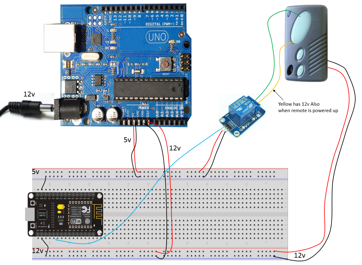
Basically I am using an Arduino Uno and a Nodemcu.
The only reason I use the arduino uno is to seperate the 12v from 5v power supply. I need 5v for the Nodemcu and 12v to power the garage remote control.
I know how to setup buttons in blynk and have that communicate with nodemcu over the wifi. What I don’t know is how to physically connect the wires. Basically when the remote is powered up, the yellow wire (which represents one side of the button) has 12v on it also. The green wire has no voltage. When I touch the two momentarily together it will simulate the button push on the actual remote.
How do I wire this up on the breadboard. Preferable I’d like to add an LED to indicate when the yellow and green wires have been joined momentarily. In addition how to I protect the Nodemcu from 12v going back into it?
Hi - I’ve created a simailar setup but found it easier to use a wemos device as my complete wifi arduino mcu board. I soldered two wires from my remote control button (on the remote control pcb board) to a simple 5v relay you can get with wemos as a shield or you can separately purchase a arduino relay board from eBay. You can write a simple sketch to activate the relay from the wemos board which will short out the connections on your pcb remote control. With respect to powering the remote control I simply left the battery in the remote to make things simple (it should last over 1 year). Hope that helps.
Thanks for your response, I was hoping to use only what I have in the picture - and maybe a couple of relays if I needed it?
or is there another simpler way.
Using the Arduino as a regulated 5v or 3.3v power source is a good bench-top (aka temparary) solution when without an alternative PSU
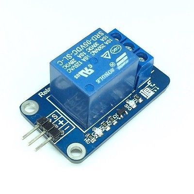
3.3v logic compatible relay modual (which usually includes an LED indicator) or a transistor circuit (which, I guess if you knew how to make, then you wouldn’t be asking… sooo, get a relay ).
Whatever you do, do NOT connect the 12v switch wire (or any standalone relay) directly to your MCU pins
I know I have lots to learn, and plan to however I was hoping to have this remote access setup asap. So I have cut a few corners.
Once this is setup and safe, I intend to educate myself. If there is something I need to fix asap for this setup to become safe - then please tell me how.
I’m not sure why the yellow wire would have 12v I would have thought it is wired to the same circuit connections as the button on the pcb and the circuit shorts the button connection on the remote pcb to simulate a physical button press when the relay connection is closed - which is being controlled from your node mcu code.
I am not sure either, but I have 3 different remote controls for 3 different gates/doors. All of the buttons have at least 12v on one side of the push button when the main remote is powered up.
Best you check with a multimeter what happens between button connection on remote control pcb - generally by pressing button is shorting out connections which is what you would be doing by closing relay for a short period of time (e.g. 2 seconds) which will simulate a button press on remote control.
Please see revised diagram at the following link, can someone please guide me to the next steps. And most importantly is it safe from any fire hazard etc.
I know if I connect the signal wires (green) directly to the nodemcu it will work, but it’s concerning as the voltage on these wires vary between -15-24vdc (red lead of multimeter on the ‘green signal wire’ from the relay and black lead on the outside of the 12v plug)
The power on the logic side of the relay board should only be 5v!! (Unless it clearly states as needing 12v to power the coils on the relays themselves - hard to see in the picture, and assuming that is the exact relay board you are using).
As to why you are seeing the transient voltages on the green “wires”… I don’t know as they should only be the 5v logic inputs from the MCU (that is what safely triggers the relays as you enable the MCU pins HIGH or LOW).
EDIT - in fact, since you are “seeing” negative voltages, I would suspect simple transients or ground leakage. Just hook up one of the green wires at a time (to the appropriate MCU pin) and test.
Many of these remotes use a mini, micro amp, 12v battery (like an A23 or LR23A) to better facilitate the RF transmission power. Thus the entire circuit is 12v, even across the switch… therefor the need for a relay when hard-wiring the remote into an MCU environment.
All I have done is simply soldered two sides of the each remote control button. It turns out that the Yellow wires coming out of the remotes are carrying 12v. This happens when I connect 12v power supply for the remotes. I have soldered red/black to where the battery used to slot in.
So without plugging the 2 wires from the remote into the relay I have 12v on one leg. This happens on both remotes so I assume that is normal.
Now when I connect it as per diagram and leave the green wires unconnected, there is a negative voltage on them. If I plug the green wires into the breadboard ie direct connection to the digital outputs of the NODEMCU then it works as expected.
However this voltage on the green wires still exists whether it’s connected to the D/O’s of the NODEMCU or not.
It works as it should, I have tested each relay one by one and all together however my ‘box’ feels a little hot/warm and it concerns me!
All is good on the relay… it needs the 12v due to the power requirements on the relay coils. The logic is still 5v. And as best as I can tell, you shouldn’t need to worry about the transient voltage readings… particularly as they are in the negatives; that tells me it is probably just low micro-current leakage in the grounds. - but don’t go canceling your house insurance just cuz I said so
As for the warmth… where exactly is this coming from… what box?
Make sure that your relays only need to be “activated” momentarily, so as not to tax your Arduino’s current flow on the VIN port. Hook up to the normally open connections on the relays and toggle the MCU pins accordingly to make them drive the relays into the Closed position only long enough to trigger the switch.
I have basically just shoved these components into a case, that I intend to seal off. Do these components need to be ventilated?
I have hooked things up to normally open and when pressing a button I only make sure I hold it down for about half a second - but that leads to my next question
How Can I make the button a ‘switch’ (that bit I know via the app) but only for 500ms, then to switch off automatically?
Additionally in the event of a power failure how can I ensure that when power is restored pins are low and not high?


