Excuse me, I have arduino Uno + ESP8266, how did you connect it to BLYNK?
I don’t know how to do it.
@El-cata-caldos please don’t add unrelated questions on to existing topics. I’ve moved this to it’s own topic.
Are you looking for wiring diagrams or code? Either way, searching this forum will provide all the information you need.
Pete.
I need to know how to edit this code.
when Blynk.run it starts to run, nothing I write in the code works
What can I do to edit it and what I want to write works?
**********************************************************
  Download latest Blynk library here:
    https://github.com/blynkkk/blynk-library/releases/latest

  Blynk is a platform with iOS and Android apps to control
  Arduino, Raspberry Pi and the likes over the Internet.
  You can easily build graphic interfaces for all your
  projects by simply dragging and dropping widgets.

    Downloads, docs, tutorials: http://www.blynk.cc
    Sketch generator:           http://examples.blynk.cc
    Blynk community:            http://community.blynk.cc
    Social networks:            http://www.fb.com/blynkapp
                                http://twitter.com/blynk_app

  Blynk library is licensed under MIT license
  This example code is in public domain.

 *************************************************************
  This example shows how to use Arduino Ethernet shield (W5100)
  to connect your project to Blynk.

  NOTE: Pins 10, 11, 12 and 13 are reserved for Ethernet module.
        DON'T use them in your sketch directly!

  WARNING: If you have an SD card, you may need to disable it
        by setting pin 4 to HIGH. Read more here:
        https://www.arduino.cc/en/Main/ArduinoEthernetShield

  Feel free to apply it to any other example. It's simple!
 *************************************************************/

/* Comment this out to disable prints and save space */
#define BLYNK_PRINT Serial

#include <SPI.h>
#include <Ethernet.h>
#include <BlynkSimpleEthernet.h>

// You should get Auth Token in the Blynk App.
// Go to the Project Settings (nut icon).
char auth[] = "";

#define W5100_CS  10
#define SDCARD_CS 4

void setup()
{
  // Debug console
  Serial.begin(9600);

  pinMode(SDCARD_CS, OUTPUT);
  digitalWrite(SDCARD_CS, HIGH); // Deselect the SD card

  Blynk.begin(auth);
  // You can also specify server:
  //Blynk.begin(auth, "blynk-cloud.com", 80);
  //Blynk.begin(auth, IPAddress(192,168,1,100), 8080);
  // For more options, see Boards_Ethernet/Arduino_Ethernet_Manual example
}

void loop()
{
  Blynk.run();
}
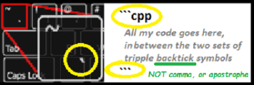
@El-cata-caldos please edit your post, using the pencil icon at the bottom, and add triple backticks at the beginning and end of your code so that it displays correctly.
Triple backticks look like this:
```
Pete.

Go back to the Sketch builder and choose Uno as your board and ESP8266 WiFi Shield as your connection type.
Read the comments in the code and enable Software Serial as you are using an Uno, and disable Serial1.
You should also reduce the baud rate to 9600 and configure your ESP8266 to communicate at this speed using an AT command.
If you get stuck along the way the search the forum for UNO + ESP-01.
Pete.
Thanks for your reply.
But I need to know how to edit the code in blynk.
I want to know how to modify functions in virtualpins.
I need the virtual pin that controls one output to light for a few seconds and that when this output is active, another output cannot be activated.
How can I edit the code?
through this function?
BLYNK_WRITE(V5) // V5 is the number of Virtual Pin { int pinValue = param.asInt();}
BLYNK_WRITE(V5) is a callback function that is triggered whenever the value of the widget connected to Virtual Pin 5 changes in the app.
The code that is in that function will execute whenever the Blynk server detects a change of value of V5.
Pete.
But this instruction
BLYNK_WRITE(V5) // V5 is the number of Virtual Pin { int pinValue = param.asInt();}
widget (0 … 100) on Virtual Pin V1
I need to be able to read the status of the Virtual Pin status and know if it is a 1 or a 0, (not a state between 0 and 100) depending on this, the outputs are supported in the way you choose.
How can I do this to know if the Virtual Pin is sending a 1 or 0?
Thank you
You get the value from the widget using the param.as… function.
Depending on the type of incoming data from the widget, that can be param.asInt, param.asFloat, param.asString etc.
In the case of a simple two-state button widget, you’ll want to use param.asInt()
The code could look something like this…
BLYNK_WRITE(V5)
{
  int pinValue = param.asInt();
  If(pinValue == 1)
  {
    // the switch widget is on, do some on related stuff
  }
  else
  {
    // the switch widget is off, do some off stuff
  }
}
Pete.
Thanks for your reply.
This I think is what I was looking for. I understand what it says but still I can’t get it to work I don’t understand what my fault is.
What am I doing wrong?
It is as if everything written before Blynk.run was ignored
#define BLYNK_PRINT Serial

#define Abrir 2  // Nombre para el led en el pin 2
#define Cerrar 3  // Nombre para el led en el pin 3
boolean PUL; // variable donde guardo estado del pulsadores
int Tiempo = 32000; // Tiempo de funcionamiento

#include <SPI.h>
#include <Ethernet.h>
#include <BlynkSimpleEthernet.h>

// Deberías obtener el token de autenticación en la aplicación Blynk.
// Ir a la configuración del proyecto (icono de tuerca).
char auth[] = "";

#define W5100_CS  10
#define SDCARD_CS 4

// Esta función se llamará cada vez que deslice el widget
// en la aplicación Blynk escribe valores en el Pin virtual V1
BLYNK_WRITE(V1)
{
  int pinValue = param.asInt(); // asignar valor entrante del pin V1 a una variable
  // procesar el valor recibido
  if (pinValue == 1)
  {
      digitalWrite (Abrir , HIGH);// el widget de interruptor abrir está activado durante el tiempo indicado
    delay (Tiempo);
    digitalWrite (Abrir, LOW);
  }
  else
  {
   digitalWrite (Abrir, LOW); // el widget de interruptor abrir está apagado
  }
}
BLYNK_WRITE(V2)
{
  int pinValue = param.asInt(); // asignar valor entrante del pin V1 a una variable
  // procesar el valor recibido
  if (pinValue == 1)
  {
      digitalWrite (Cerrar, HIGH);
    delay (Tiempo);
    digitalWrite (Cerrar, LOW);  // el widget de interruptor cerrar está activado durante el tiempo indicado
  }
  else
  {
   digitalWrite (Cerrar, LOW); // // el widget de interruptor abrir está activado
  }
}


void setup()
{
  pinMode (Abrir, OUTPUT);
  pinMode (Cerrar, OUTPUT);


  // ahora es Estado inicial (todas apagadas)
  digitalWrite (Abrir,LOW); // (para que la salida 2 este apagada)
  digitalWrite (Cerrar,LOW); // (para que la salida 3 este apagada)
  // Consola de depuración
  Serial.begin(9600);


  pinMode(SDCARD_CS, OUTPUT);
  digitalWrite(SDCARD_CS, HIGH); //Anule la selección de la tarjeta SD

  Blynk.begin(auth);

// También puedes especificar el servidor:
  //Blynk.begin(auth, "blynk-cloud.com", 80);
  //Blynk.begin(auth, IPAddress (192,168,1,100), 8080);
}

void loop()
  {
  Blynk.run();
}
`` `What exactly does this mean?
Is your board connecting to Blynk?
This delay…
will cause Blynk to disconnect, read this:
Pete.
No, the arduino uno does not disconnect, I mean that what I want to do does not work, the code that I write is completely ignored by the arduino. only blynk.run is run, what I write no. can you tell me why?
Blynk.run() is a blocking function - it will try to connect to Blynk and if this unsuccessful then the code execution will stop at that point.
If, as you’ve said in the topic title and in your first post within the topic, you are using an Arduino Uno and an ESP-01 as a WiFi shield then the code you’ve posted will NEVER connect to Blynk, as it is attempting to make the connection via an Ethernet shield - which you don’t have.
When, as I suggested in post #5, you go back to the Sketch Builder and generate the base code for your actual hardware setup then you might stand a chance of getting connected to your WiFi and then to Blynk.
Pete.
Sorry for the misunderstanding.
No, I could not use the arduino uno + ESP8266 board because I cannot connect it with blynk. Currently as seen in the code I sent I am using arduino uno with ethernet w5100 shield. This works for me with the basic example, but I need to add functions.
Clarified this I insist the code that I write is ignored, it does not put the outputs at low level at the beginning for example and activates the 2 when the arduino starts, when I indicate that they are at low level in my code, it ignores all that and everything else I write. Why does this happen?
Is there any place where I can get more information in an orderly way about how blynk works and the terms I should use to communicate with him?
excuse me for all the trouble I’m causing you
So what does your serial monitor show?
Pete.
loading this the this code in the way indicated in the examples with blynk and leaving void loop free for blynk.run.
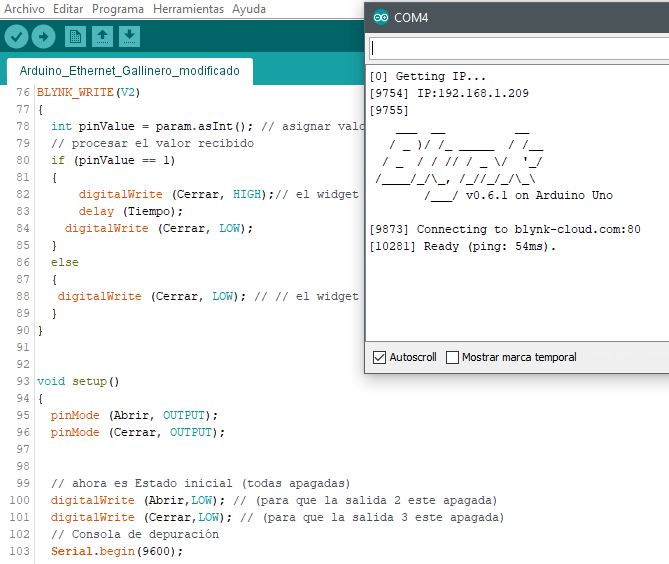
correct connection with the app
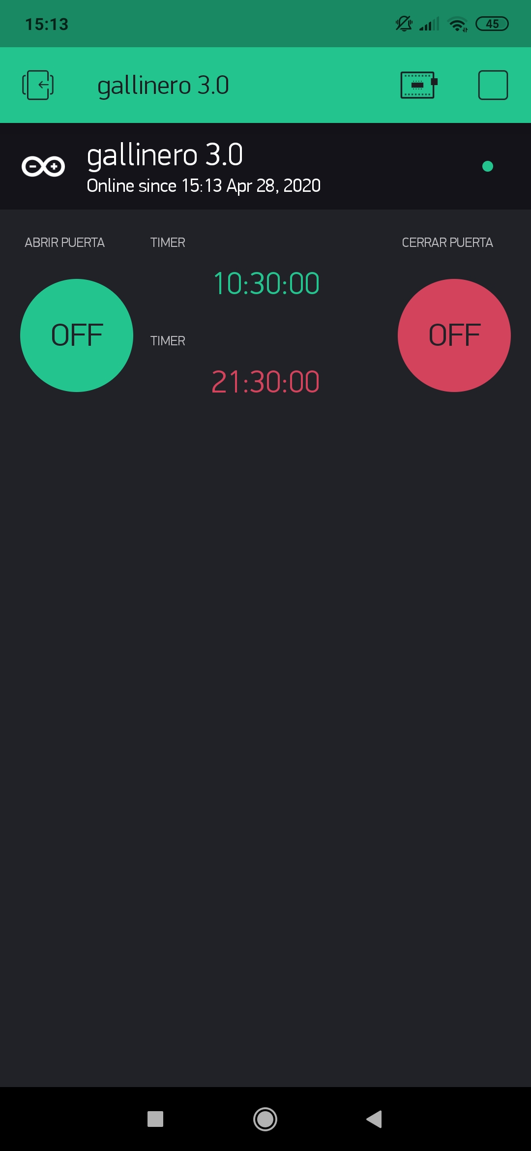
but only the example code works, nothing that I wrote.
#define BLYNK_PRINT Serial

#define Abrir 2  // Nombre para el led en el pin 2
#define Cerrar 3  // Nombre para el led en el pin 3
boolean PUL; // variable donde guardo estado del pulsadores
int Tiempo = 32000; // Tiempo de funcionamiento

#include <SPI.h>
#include <Ethernet.h>
#include <BlynkSimpleEthernet.h>

// Deberías obtener el token de autenticación en la aplicación Blynk.
// Ir a la configuración del proyecto (icono de tuerca).
char auth[] = "";

#define W5100_CS  10
#define SDCARD_CS 4

// Esta función se llamará cada vez que deslice el widget
// en la aplicación Blynk escribe valores en el Pin virtual V1
BLYNK_WRITE(V1)
{
  int pinValue = param.asInt(); // asignar valor entrante del pin V1 a una variable
  // procesar el valor recibido
  if (pinValue == 1)
  {
      digitalWrite (Abrir , HIGH);// el widget de interruptor abrir está activado durante el tiempo indicado
    delay (Tiempo);
    digitalWrite (Abrir, LOW);
  }
  else
  {
   digitalWrite (Abrir, LOW); // el widget de interruptor abrir está apagado
  }
}
BLYNK_WRITE(V2)
{
  int pinValue = param.asInt(); // asignar valor entrante del pin V1 a una variable
  // procesar el valor recibido
  if (pinValue == 1)
  {
      digitalWrite (Cerrar, HIGH);
    delay (Tiempo);
    digitalWrite (Cerrar, LOW);  // el widget de interruptor cerrar está activado durante el tiempo indicado
  }
  else
  {
   digitalWrite (Cerrar, LOW); // // el widget de interruptor abrir está activado
  }
}


void setup()
{
  pinMode (Abrir, OUTPUT);
  pinMode (Cerrar, OUTPUT);


  // ahora es Estado inicial (todas apagadas)
  digitalWrite (Abrir,LOW); // (para que la salida 2 este apagada)
  digitalWrite (Cerrar,LOW); // (para que la salida 3 este apagada)
  // Consola de depuración
  Serial.begin(9600);


  pinMode(SDCARD_CS, OUTPUT);
  digitalWrite(SDCARD_CS, HIGH); //Anule la selección de la tarjeta SD

  Blynk.begin(auth);

// También puedes especificar el servidor:
  //Blynk.begin(auth, "blynk-cloud.com", 80);
  //Blynk.begin(auth, IPAddress (192,168,1,100), 8080);
}

void loop()
  {
  Blynk.run();
}
`` `As I’ve already said, having a 32 second delay will cause Blynk disconnections.
I was more interested in what the serial monitor showed when you ran your code. But, please don’t post screenshots of your serial output, copy and paste it instead - in the same way you would with code, using triple backticks.
Pete.
I just want to do the following:
at the start low level outputs
when i press the button in the app, output active for 35, 40 seconds
if one output is active the other can never be active
Then you should research timeout timers.
That’s what your code should be doing, but I suspect other things are happening to change this. However, without seeing the serial output from your code it’s difficult to say.
Pete.