Hello,
it might sound like a weird question, but how do you share a ground. My Arduino Nano doesn’t output enough current for the esp8266, so I use an external power source. The Problem is, as soon as I connect vcc, chpd and ground to the power adapter, the Esp8266 isn’t responding in the Blynk sketch. (I also tested it with my Mega, where it works with the 3.3 V, and it didn’t work with the power adapter).
But somewhere in this forum I read, to get the Esp8266 to work with an External Power source, is to share a ground. And unfortunately I have no idea how that works, I already fried one ESP in the process of finding out.
Thank you in advance
The arduino might not be outputting enough power to the esp8266. And of course, an esp8266 can be powered via external power sources. I also power all my ESPs via 5V power adapters for almost all my projects.
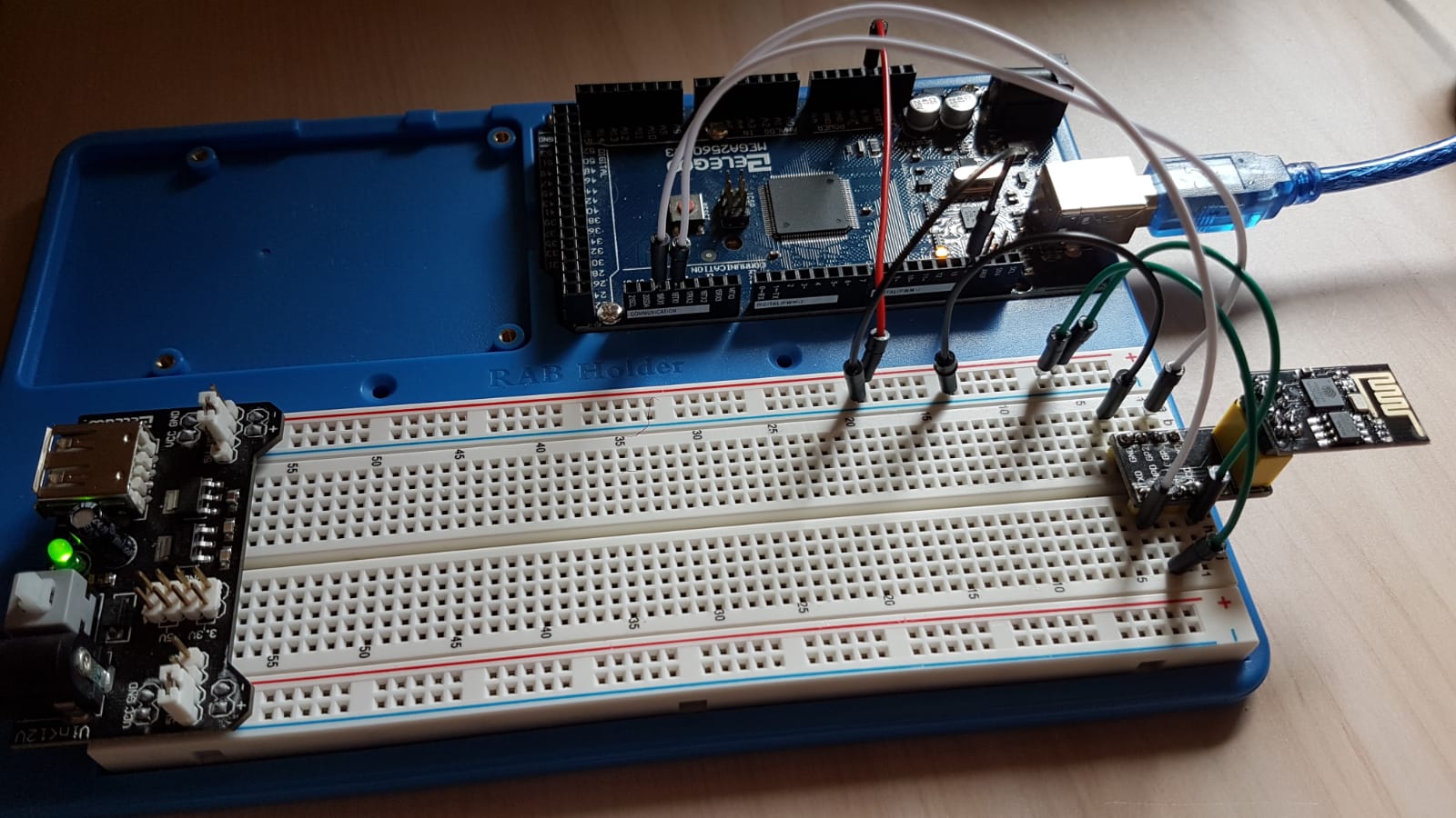
But here, I guess that there is something wrong going on with the connections itself. So, can you somehow show that how you are connecting everything together ?
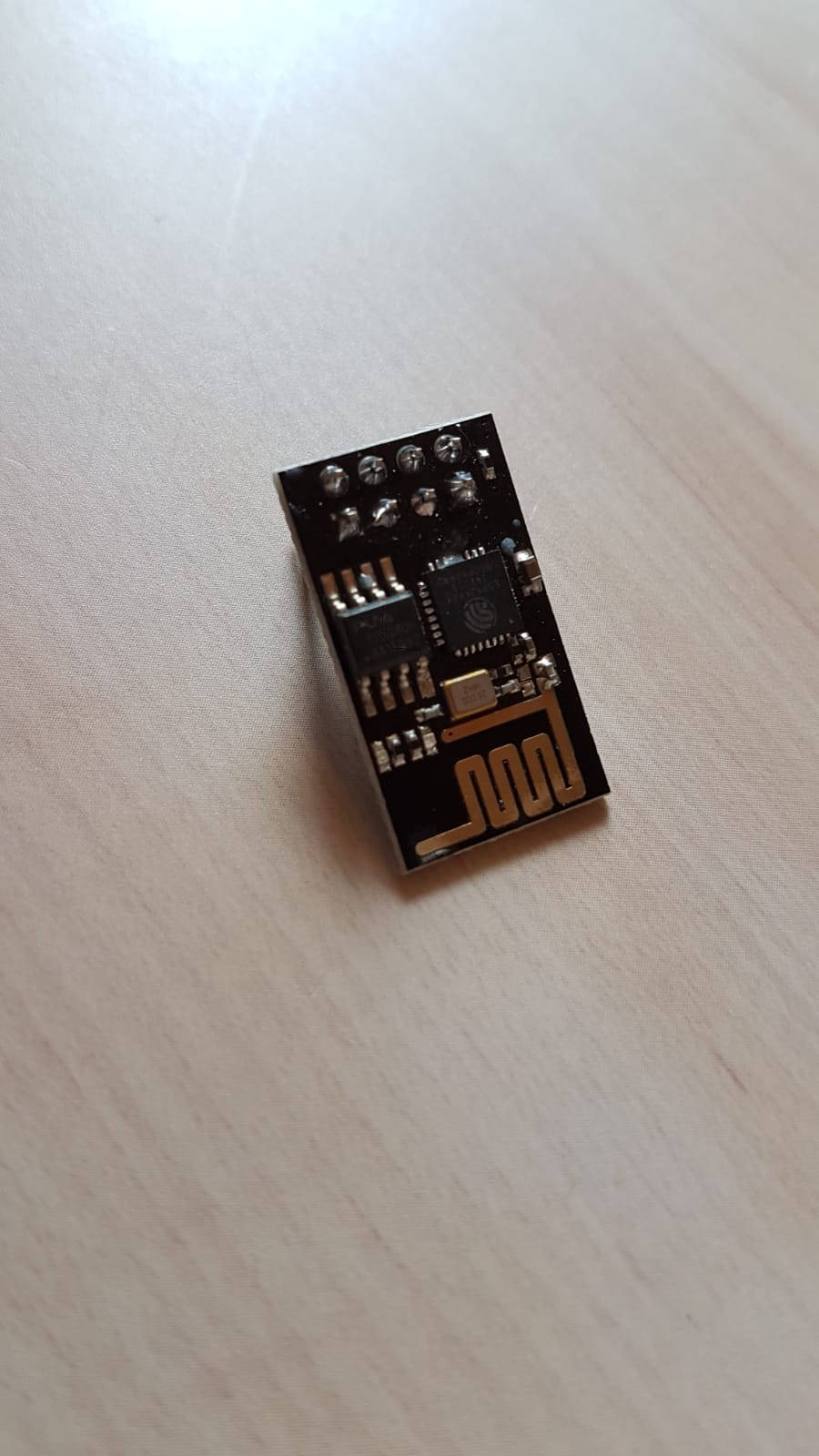
Also, I would like to know that which ESP8266 are you using exactly (You can also provide an image).
Thank you for your answer!
In this image you can see the configuration which works for me. The two white jumpers are my TX/RX, the two green ones for VCC / CH_PD and the first black one for the ground pin of the ESP. I connected VCC and CH_PD to the 3.3V output of the Mega (Red cable) and the ground rail to ground (2nd black cable)
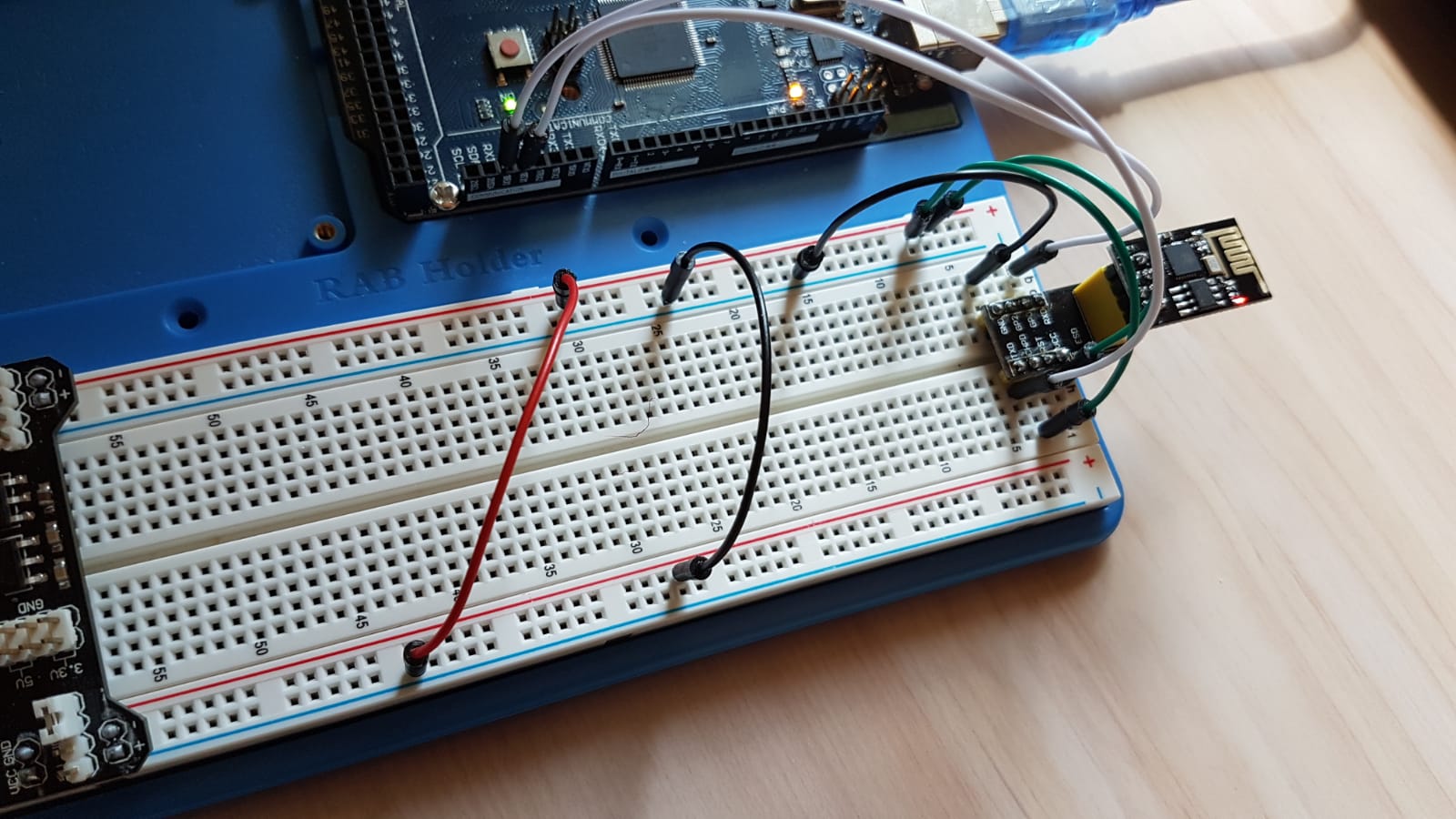
And in this image it doesn’t work. The only thing I changed was to connect the red cable to the 3.3V rail of my power supply and the 2nd black cable to the ground rail of my power supply. And suddenly, it doesn’t work anymore.
This is the ESP I am using:
Kind regards
If you look carefully at your breadboard PSU, you’ll see that it’s power output pins are labelled + and -, but that the minus symbol is next to the bus rail with the red stripe, and the plus symbol is next to the rail with the black stripe.
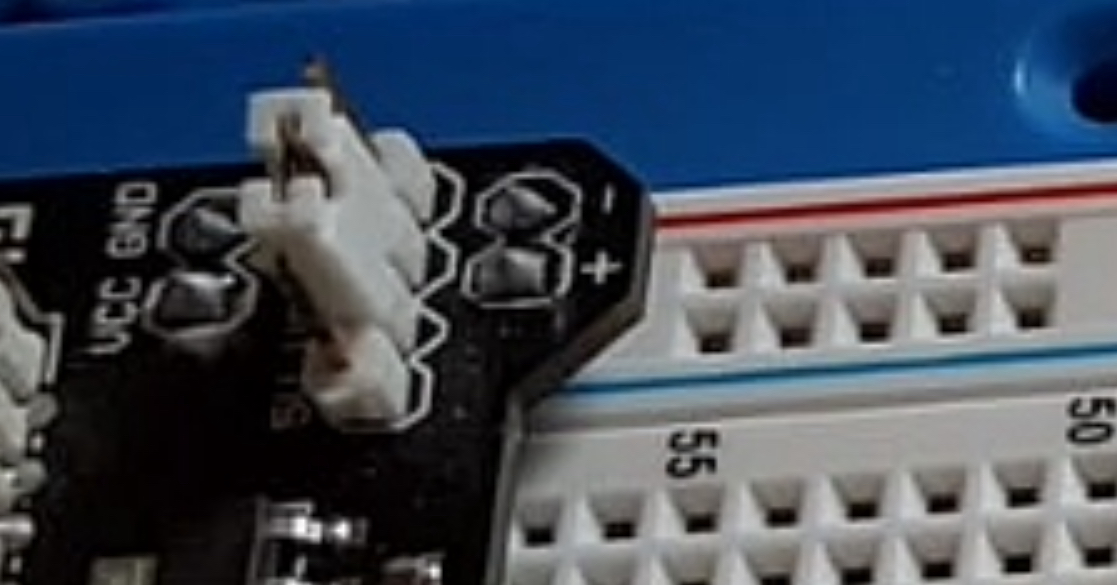
You appear to be following the colours on the bus rails, not the polarity of the PSU.
Sharing a ground simply means ensuring the the negative outputs from all the power supplies are connected together.
Pete.
1 Like
Thank you for your answer Pete,
But I am aware of the fact, that the colors of the rails don’t match the polarity of my power supply, that’s why I deactivated it on the top rails, so that only the bottom rails are supplied with power.
How I exactly would I have to realise sharing a ground? Should I connect the ground of the supply to the ground of the arduino?
Why don’t you simply rotate the power supply 180°?
Yes.
Pete.
That would be kind of uncormfortable regarding my desk setup
I connected both grounds, and now it works. But I don’t really understand why that is that way?
Because physics… To keep it dirt simple, circuits with differing voltage potentials need a common reference… a shared ground… else they can potentially leak across each other from a higher source to a lower source… or just not work at all.
Google for more head twisting info ![]()
That board is just sticky taped to the base, and those rails can be removed and swapped around. Lots of solutions, including just knowing what you are doing is supposed to be backwards… but when sharing with others, having something so ‘wrong’ adds to the confusion.