I am trying to make my first arduino simple project based on the directions of this video for a gift to my fiancee https://www.youtube.com/watch?v=duiAbLsXZSE&ab_channel=Breaks%27n%27Makes
You may watch it so you can understand better.
It uses the app Blynk.
I follow his directions exactly but I made one change: I use a WS2811 led strip with a 12V-1A power supply so I power the LED strip from the power supply by soldering it on the step down converter’s inputs.
Long story short, I fried 2 Wemos. Maybe it was my fault because I accidentally put wrong wire to the wrong input. I dont remember tbh.
The connections are fine.
Here was the circuit:
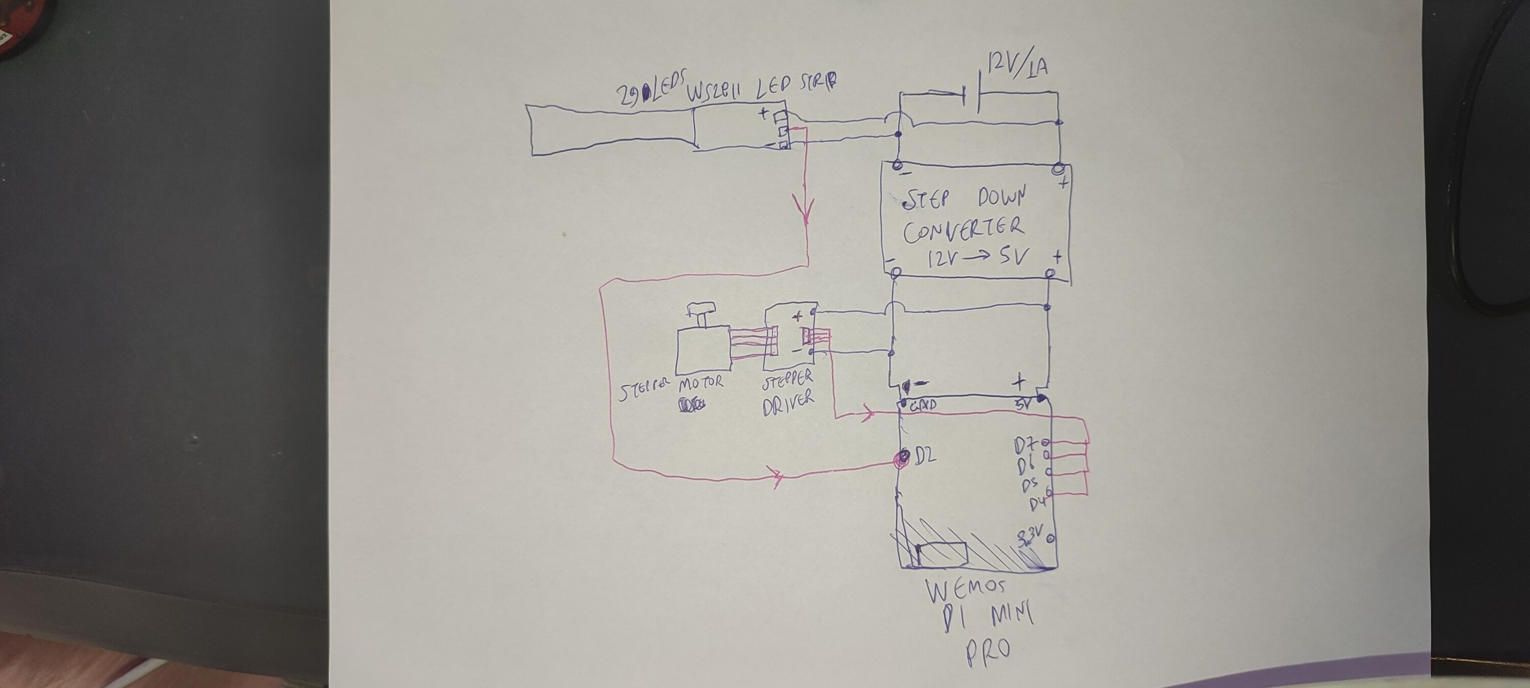
Here is the code:
#include <SPI.h>
#include <BlynkSimpleEsp8266.h>
#include <ESP8266WiFi.h>
#include <Stepper.h>

#define PIN D2
#define NUMPIXELS 60
#define BLYNK_PRINT Serial

int motorSpeed;
int motorDirection;

const int stepsPerRevolution = 4096;

BlynkTimer timer;
Stepper myStepper(stepsPerRevolution, 14, 12, 13, 15);
Adafruit_NeoPixel pixels = Adafruit_NeoPixel(NUMPIXELS, PIN, NEO_GRB + NEO_KHZ800);

void stepperControl() {
  if (motorSpeed > 0) {
    if (motorDirection == 0) {  // Rotate Clockwise
      myStepper.step(stepsPerRevolution / 50);
    } else {  // Rotate CounterClockwise
      myStepper.step(-stepsPerRevolution / 50);
    }
  }
}

void setup()
{
  Serial.begin(9600);
  timer.setInterval(1, stepperControl);
  Blynk.begin("XXXXXXXXXXXXXXXXXXXXXXXXXXXXXXXXXXXXX", "XXXXXXXXXXXXXXXXX", "XXXXXXXXXXXXXX");
  pixels.begin();
  pixels.setBrightness(55);
}

void loop()
{
  Blynk.run();
  timer.run();
}


BLYNK_WRITE(V0)
{
  motorSpeed = param.asInt();
  myStepper.setSpeed(motorSpeed);
}


BLYNK_WRITE(V2)
{

  int R = param[0].asInt();
  int G = param[1].asInt();
  int B = param[2].asInt();
  Serial.println(R);
  Serial.println(G);
  Serial.println(B);
  for (int i = 0; i < NUMPIXELS; i++) {

    pixels.setPixelColor(i, pixels.Color(R, G, B));

    pixels.show();
  }
}
I gave a shot at it again.
Removed the led strip from the equation, to simplify things.
Bought a new same Wemos.
- The sketch uploads successfully again.
- Voltage measurements seem fine before the wemos is connected.
- When Wemos is connected to the circuit, Voltage across the 5V input of the Wemos as long as positive output of the step down converter becomes about 3.4V (!!!). Even though before wemos, the voltage is at 5V!
- Stepper driver lights come on except the 4th one. Stepper motor not rotating.
Note: When connected from the USB, the lights of the stepper driver dont even light on.
The connections of the inputs of the stepper driver are correct since I copied them from the tutorial.
Also, the Wemos gets kind of hot.
Here is another video of a failed attempt:
At my wit’s end.
Help.