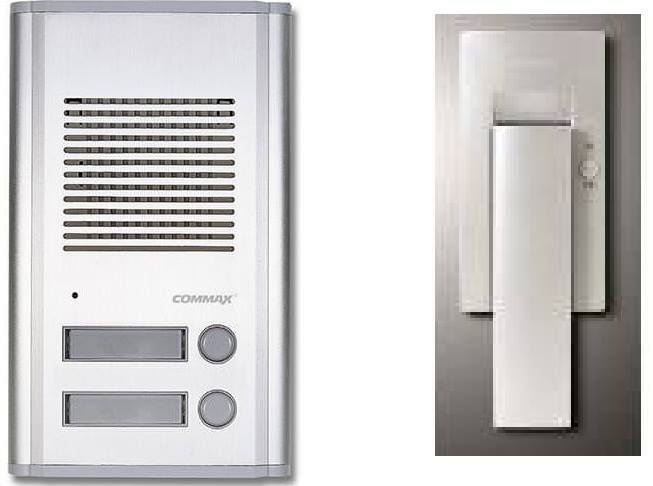
To operate an 6-12V electromagnetic latch, which standard is operated from the intercom button, I use a relay on the four-relay module in parallel with the intercom button.
The relay is commanded by a ESP8266-12F Witty Cloud. With a command from iphone (button widget, set to “push”, 1 to 0).
On the same board, through the other three relays, they give similar commands the lights.
In the event of a power failure, when the electricity returns, the latch remains connected until the first command on the phone (if pressed on the intercom, it does not react). In the case of lights I have no problem, and generally the system behaves ok.
For lights, use GP16, GP14, GP2 and for latch GP5.
I have to check the digital outputs on the board, possibly change the two outputs (ex. GP5 with GP16)
I’m not sure what is the cause, but the the problem is that the bobbin coil (latch) remains continuously fed. unlocking can only be done on the phone. Today I noticed this after the tension dropped after a short period of time.
gpio 5 should be ok for the latch. the question is, you have an active high or active low relay board?
maybe the board has reversed logic, and this is why the relay is activated at startup. try to reverse the logic in the blynk button: for off set 1 and for on set 0.
but, even better, to avoid keeping the latch “on” in case of restart and there is no wifi / internet / server connection, is to turn off the relay right in the setup with digitalwrite, BEFORE attempting to connect to blynk server!
actually, you should always set all the outputs in the desired default state before initing blynk connection.
I tried to change pins assignments at buttons, but the issues remained at the same button, with the changed digital pin.
e.q.: #first, the button (green - doesn’t matter color) assigned to door latch, has digital pin GP5 = relay start when power on module ESP, and relay stays ON. #second, change pin of the same button(green) to GP15, problem migrate to GP15, and corresponding relay stays ON.
I removed button, create another one, set GP14, same problem.
#define BLYNK_PRINT Serial
#include "ESP8266WiFi.h"
#include "BlynkSimpleEsp8266.h"

// You should get Auth Token in the Blynk App.
// Go to the Project Settings (nut icon).
char auth[] = "xxxxxxxx";

// Your WiFi credentials.
// Set password to "" for open networks.
 char ssid[] = "xxxxxx";
char pass[] = "xxxxxxxxxx";

void setup()
 {
// Debug console
Serial.begin(9600);

pinMode(1, OUTPUT);  //here I tried to say how to go at startup, initial without this line

Blynk.begin(auth, ssid, pass);

}

void loop()
{
  digitalWrite(1, HIGH); //here I tried to say go on high mode at startup, initial without this line
Blynk.run();
}
I use digital pins
now, after switch pin assignments, I have:
Button 1 = GP5, button 2 = GP16, button 3 = GP14, button 4 = GP2
GP5 and GP16 acting OK, but, at power on board, GP2 start relay (go ON and OFF itself, acting “push”) and after a few seconds GP14 start relay and remain ON and stay ON until use phone to set OFF.
Doesn’t matter how digital pin is assigned, button 3 and 4 has issue.
Work fine from first time, for one light (just one button/one relay). Then upgraded with other three relay, adding three new buttons (one for door latch, and two more lights). Work well, with no problem until crash solenoid at door latch . I initially believed is a latch problem (10 years old ) and I bought a new one.
In one of the previous days, I noticed that the solenoid coil of latch is powered up, and I did the analogy with the power failure. I tested by power on and off and the suspicion was confirmed.
pin2 is builtin LED - I think is not so special,
pin16 is also not special (if I don’t miss something )
please see:
“I tried to change pins assignments at buttons, but the issues remained at the same button, with the changed digital pin.
e.q.: #first, the button (green - doesn’t matter color) assigned to door latch, has digital pin GP5 = relay start when power on module ESP, and relay stays ON. #second, change pin of the same button(green) to GP15, problem migrate to GP15, and corresponding relay stays ON.
I removed button, create another one, set GP14, same problem.”
you think is pins problem?
“pin2 - not so special” - my mistake, sorry Costas. In my case is very special. When I power on the board, builtin LED flash, that mean the relay receives the command.
By the way, the code with pinMode and digitalWrite line insert, do nothing…
 I have a small / big problem:
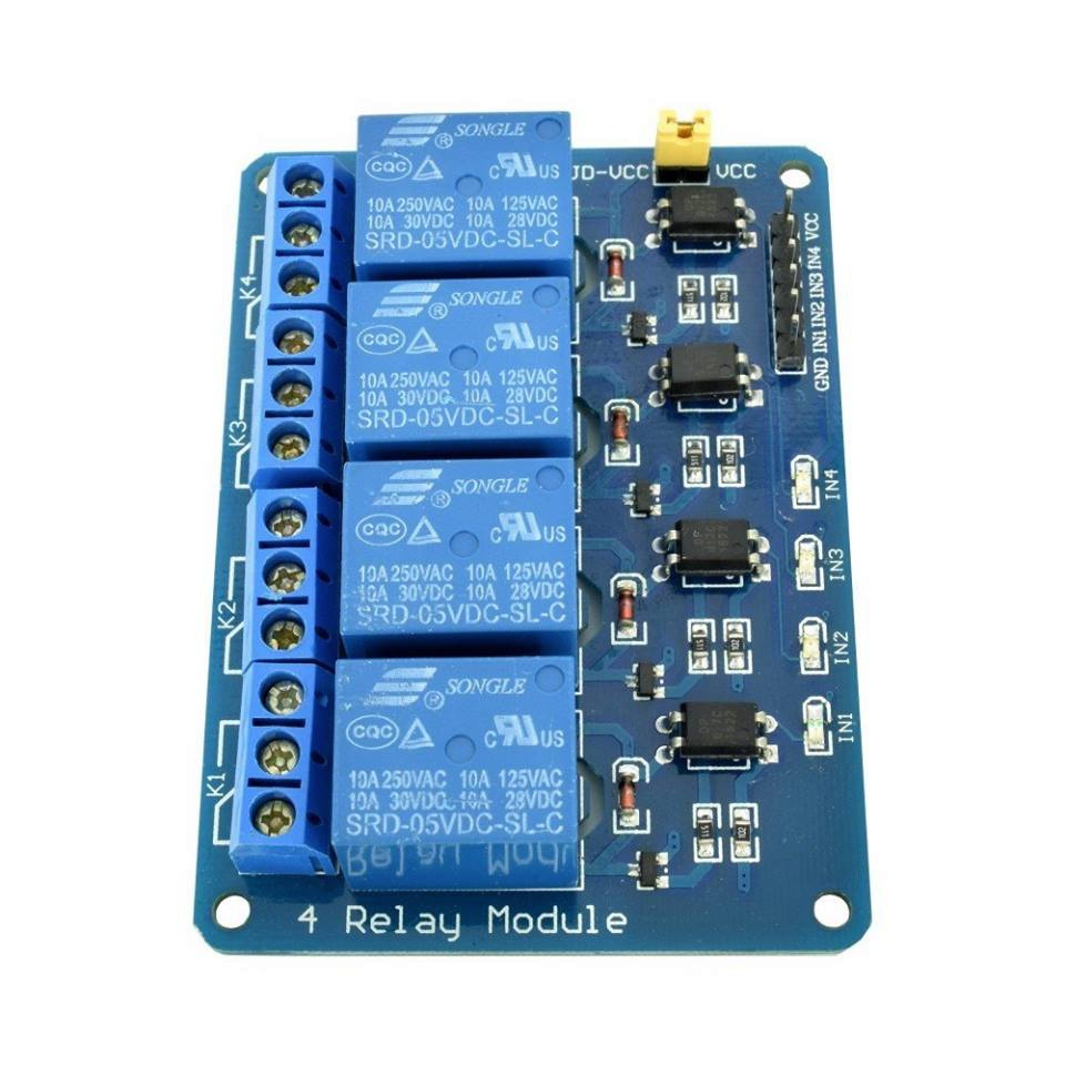

 . I initially believed is a latch problem (10 years old