Help Needed: Sending Sensor Data from ESP32-CAM to Blynk via Arduino Uno

We are working on a baby monitor system using an ESP32-CAM, which is programmed and connected to an Arduino board (Uno). Additionally, we are using a DHT11 temperature and humidity sensor and a KY-037 voice sensor. Our goal is to send the data read from these sensors (temperature, humidity, and sound level) from the Arduino Uno to the ESP32-CAM, which will then transmit this data to the Blynk app for display.

We have successfully set up the live stream feature on the Blynk app using the ESP32-CAM. However, we are struggling to find a way to establish communication between the Arduino Uno and ESP32-CAM to send sensor data to the Blynk app.

Could someone please guide us on how to achieve this communication between the Arduino Uno and ESP32-CAM, and how to send sensor data to the Blynk app for real-time monitoring of temperature, humidity, and sound level?
Or how to establish serial communication between the Arduino Uno and ESP32-CAM

Any help or insights would be greatly appreciated. Thank you!

here is the working code we’re using to do the live stream.


#define BLYNK_PRINT Serial

#include "OV2640.h"
#include <WiFi.h>
#include <WebServer.h>
#include <WiFiClient.h>
#include <BlynkSimpleEsp32.h>


// Select camera model
//#define CAMERA_MODEL_WROVER_KIT
//#define CAMERA_MODEL_ESP_EYE
//#define CAMERA_MODEL_M5STACK_PSRAM
//#define CAMERA_MODEL_M5STACK_WIDE
#define CAMERA_MODEL_AI_THINKER

#include "camera_pins.h"

char auth[] = BLYNK_AUTH_TOKEN;
const char* ssid = "";
const char* password = "";


OV2640 cam;

WebServer server(80);

const char HEADER[] = "HTTP/1.1 200 OK\r\n" \
                      "Access-Control-Allow-Origin: *\r\n" \
                      "Content-Type: multipart/x-mixed-replace; boundary=123456789000000000000987654321\r\n";
const char BOUNDARY[] = "\r\n--123456789000000000000987654321\r\n";
const char CTNTTYPE[] = "Content-Type: image/jpeg\r\nContent-Length: ";
const int hdrLen = strlen(HEADER);
const int bdrLen = strlen(BOUNDARY);
const int cntLen = strlen(CTNTTYPE);

void handle_jpg_stream(void) {
    char buf[32];
    int s;

    WiFiClient client = server.client();

    client.write(HEADER, hdrLen);
    client.write(BOUNDARY, bdrLen);

    while (true) {
        if (!client.connected()) break;
        cam.run();
        s = cam.getSize();
        client.write(CTNTTYPE, cntLen);
        sprintf( buf, "%d\r\n\r\n", s );
        client.write(buf, strlen(buf));
        client.write((char *)cam.getfb(), s);
        client.write(BOUNDARY, bdrLen);
    }
}
const char JHEADER[] = "HTTP/1.1 200 OK\r\n" \
                       "Content-disposition: inline; filename=capture.jpg\r\n" \
                       "Content-type: image/jpeg\r\n\r\n";
const int jhdLen = strlen(JHEADER);

void handle_jpg(void) {
    WiFiClient client = server.client();

    cam.run();
    if (!client.connected()) return;

    client.write(JHEADER, jhdLen);
    client.write((char *)cam.getfb(), cam.getSize());
}

void handleNotFound() {
    String message = "Server is running!\n\n";
    message += "URI: ";
    message += server.uri();
    message += "\nMethod: ";
    message += (server.method() == HTTP_GET) ? "GET" : "POST";
    message += "\nArguments: ";
    message += server.args();
    message += "\n";
    server.send(200, "text / plain", message);
}

void setup() {
    Serial.begin(115200);
     camera_config_t config;
  config.ledc_channel = LEDC_CHANNEL_0;
  config.ledc_timer = LEDC_TIMER_0;
  config.pin_d0 = Y2_GPIO_NUM;
  config.pin_d1 = Y3_GPIO_NUM;
  config.pin_d2 = Y4_GPIO_NUM;
  config.pin_d3 = Y5_GPIO_NUM;
  config.pin_d4 = Y6_GPIO_NUM;
  config.pin_d5 = Y7_GPIO_NUM;
  config.pin_d6 = Y8_GPIO_NUM;
  config.pin_d7 = Y9_GPIO_NUM;
  config.pin_xclk = XCLK_GPIO_NUM;
  config.pin_pclk = PCLK_GPIO_NUM;
  config.pin_vsync = VSYNC_GPIO_NUM;
  config.pin_href = HREF_GPIO_NUM;
  config.pin_sscb_sda = SIOD_GPIO_NUM;
  config.pin_sscb_scl = SIOC_GPIO_NUM;
  config.pin_pwdn = PWDN_GPIO_NUM;
  config.pin_reset = RESET_GPIO_NUM;
  config.xclk_freq_hz = 20000000;
  config.pixel_format = PIXFORMAT_JPEG;
    Serial.setDebugOutput(true);


   config.frame_size = FRAMESIZE_QVGA;
  config.jpeg_quality = 12;
  config.fb_count = 2;

  #if defined(CAMERA_MODEL_ESP_EYE)
  pinMode(13, INPUT_PULLUP);
  pinMode(14, INPUT_PULLUP);
#endif

    cam.init(config);

    IPAddress ip;

    WiFi.mode(WIFI_STA);
    WiFi.begin(ssid, password);
    while (WiFi.status() != WL_CONNECTED) {
        delay(500);
        Serial.print(F("."));
    }
    ip = WiFi.localIP();
    Serial.println(F("WiFi connected"));
    Serial.println("");

    // Configure Blynk
    Blynk.config(auth);
    Serial.println("Connecting to Blynk");
    while (Blynk.connect() == false) {
        delay(500);
        Serial.print(".");
    }
    Serial.println("\nConnected to Blynk");

    Serial.println(ip);
    Serial.print("Stream Link: http://");
    Serial.print(ip);
    Serial.println("/mjpeg/1");
    server.on("/mjpeg/1", HTTP_GET, handle_jpg_stream);
    server.on("/jpg", HTTP_GET, handle_jpg);
    server.onNotFound(handleNotFound);
    server.begin();


}

void loop() {
    Blynk.run();

    // Handle web server client
    server.handleClient();


}

BLYNK_WRITE(V1) {
    // When the Video Streaming widget receives a request, send the camera stream
    if (param.asInt() == 1) {
        // Capture a frame from the camera
        camera_fb_t *fb = esp_camera_fb_get();
        if (fb) {
            // Convert the frame buffer to uint8_t*
            uint8_t *frameBuffer = fb->buf;
            // Send the frame to the Video Streaming widget
            Blynk.virtualWriteBinary(V1, frameBuffer, fb->len);
            // Release the frame buffer
            esp_camera_fb_return(fb);
        }
    }
}
My first question is WHY?

Why have you connected these sensors to an Uno and not directly to the ESP32 CAM board.
And why choose a crappy sensor like the DHT11 for this application?

Pete.

Our DHT11 sensor was provided by our university, and that’s what we have. We’re using Arduino Uno because there aren’t enough ports on ESP32-CAM. We plan to add more sensors later, so we want to set up this connection for easier integration.

Any advice on connecting ESP32-CAM and Arduino Uno to send sensor data to Blynk app would be great. Thanks!

You’d be far better using a port expander than the Uno.

Can’t give any advice on your current setup I’m afraid.

Pete.

if you really have to stick to the Uno-ESPCam HW configuration, then I2C comm between them is one of your options.

1 Like

Solution Found for ESP32-CAM and Arduino Communication

Hello Blynk Community,

I wanted to share that we’ve successfully found a solution to establish communication between the Arduino Uno and ESP32-CAM for our baby monitor project. As mentioned in my previous post, we are using a DHT11 temperature and humidity sensor, a KY-037 voice sensor, and an ESP32-CAM programmed with live stream functionality on the Blynk app.

For anyone facing a similar challenge, here is an overview of the circuits we used and the code for establishing communication and transmitting sensor data to the Blynk app:

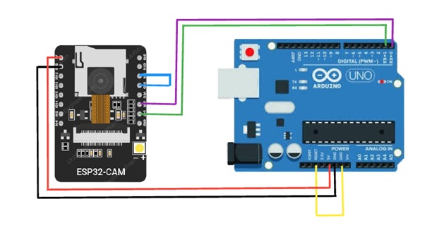
WhatsApp Image 2024-05-08 Ă  12.45.15_27ac5dea

We used the circuit above to program the ESP32-CAM using serial communication (TX/RX). By connecting the TX pins of the Arduino Uno to the RX pin of the ESP32-CAM and the RX pin of the Arduino Uno to the TX pin of the ESP32-CAM, we can establish bidirectional communication for uploading code and communication between the two devices. The code uploaded to the ESP32-CAM was designed to create a baby monitor, capturing continuous images and monitoring data such as temperature, humidity, and sound, sending notifications via Blynk in case of abnormal conditions.
and this is the code we used for this:

#define BLYNK_TEMPLATE_ID ""
#define BLYNK_TEMPLATE_NAME ""
#define BLYNK_AUTH_TOKEN ""

#define BLYNK_PRINT Serial

#include "OV2640.h"
#include <WiFi.h>
#include <WebServer.h>
#include <WiFiClient.h>
#include <BlynkSimpleEsp32.h>
#include <ArduinoJson.h>

#include <SoftwareSerial.h>

SoftwareSerial mySerial(15, 14); // RX, TX
// Select camera model

#define CAMERA_MODEL_AI_THINKER

#include "camera_pins.h"

char auth[] = BLYNK_AUTH_TOKEN;
const char* ssid = "";
const char* password = "";

OV2640 cam;
WebServer server(80);

const char HEADER[] = "HTTP/1.1 200 OK\r\n" \
                      "Access-Control-Allow-Origin: *\r\n" \
                      "Content-Type: multipart/x-mixed-replace; boundary=123456789000000000000987654321\r\n";
const char BOUNDARY[] = "\r\n--123456789000000000000987654321\r\n";
const char CTNTTYPE[] = "Content-Type: image/jpeg\r\nContent-Length: ";
const int hdrLen = strlen(HEADER);
const int bdrLen = strlen(BOUNDARY);
const int cntLen = strlen(CTNTTYPE);

void handle_jpg_stream(void) {
    char buf[32];
    int s;

    WiFiClient client = server.client();

    client.write(HEADER, hdrLen);
    client.write(BOUNDARY, bdrLen);

    while (true) {
        if (!client.connected()) break;
        cam.run();
        s = cam.getSize();
        client.write(CTNTTYPE, cntLen);
        sprintf( buf, "%d\r\n\r\n", s );
        client.write(buf, strlen(buf));
        client.write((char *)cam.getfb(), s);
        client.write(BOUNDARY, bdrLen);
    }
}
const char JHEADER[] = "HTTP/1.1 200 OK\r\n" \
                       "Content-disposition: inline; filename=capture.jpg\r\n" \
                       "Content-type: image/jpeg\r\n\r\n";
const int jhdLen = strlen(JHEADER);

void handle_jpg(void) {
    WiFiClient client = server.client();

    cam.run();
    if (!client.connected()) return;

    client.write(JHEADER, jhdLen);
    client.write((char *)cam.getfb(), cam.getSize());
}

void handleNotFound() {
    String message = "Server is running!\n\n";
    message += "URI: ";
    message += server.uri();
    message += "\nMethod: ";
    message += (server.method() == HTTP_GET) ? "GET" : "POST";
    message += "\nArguments: ";
    message += server.args();
    message += "\n";
    server.send(200, "text / plain", message);
}

void setup() {
    Serial.begin(115200);
    mySerial.begin(115200);
    camera_config_t config;
    config.ledc_channel = LEDC_CHANNEL_0;
    config.ledc_timer = LEDC_TIMER_0;
    config.pin_d0 = Y2_GPIO_NUM;
    config.pin_d1 = Y3_GPIO_NUM;
    config.pin_d2 = Y4_GPIO_NUM;
    config.pin_d3 = Y5_GPIO_NUM;
    config.pin_d4 = Y6_GPIO_NUM;
    config.pin_d5 = Y7_GPIO_NUM;
    config.pin_d6 = Y8_GPIO_NUM;
    config.pin_d7 = Y9_GPIO_NUM;
    config.pin_xclk = XCLK_GPIO_NUM;
    config.pin_pclk = PCLK_GPIO_NUM;
    config.pin_vsync = VSYNC_GPIO_NUM;
    config.pin_href = HREF_GPIO_NUM;
    config.pin_sscb_sda = SIOD_GPIO_NUM;
    config.pin_sscb_scl = SIOC_GPIO_NUM;
    config.pin_pwdn = PWDN_GPIO_NUM;
    config.pin_reset = RESET_GPIO_NUM;
    config.xclk_freq_hz = 20000000;
    config.pixel_format = PIXFORMAT_JPEG;
    Serial.setDebugOutput(true);

    config.frame_size = FRAMESIZE_QVGA;
    config.jpeg_quality = 12;
    config.fb_count = 2;

#if defined(CAMERA_MODEL_ESP_EYE)
    pinMode(13, INPUT_PULLUP);
    pinMode(14, INPUT_PULLUP);
#endif

    cam.init(config);

    IPAddress ip;

    WiFi.mode(WIFI_STA);
    WiFi.begin(ssid, password);
    while (WiFi.status() != WL_CONNECTED) {
        delay(500);
        Serial.print(F("."));
    }
    ip = WiFi.localIP();
    Serial.println(F("WiFi connected"));
    Serial.println("");

    // Configure Blynk
    Blynk.config(auth);
    Serial.println("Connecting to Blynk");
    while (Blynk.connect() == false) {
        delay(500);
        Serial.print(".");
    }
    Serial.println("\nConnected to Blynk");

    Serial.println(ip);
    Serial.print("Stream Link: http://");
    Serial.print(ip);
    Serial.println("/mjpeg/1");
    server.on("/mjpeg/1", HTTP_GET, handle_jpg_stream);
    server.on("/jpg", HTTP_GET, handle_jpg);
    server.onNotFound(handleNotFound);
    server.begin();
}

void loop() {
    Blynk.run();

    // Handle web server client
    server.handleClient();
    String jsonStr = Serial.readStringUntil('\n'); // Read data from SoftwareSerial until newline character

    // Parse JSON data
    StaticJsonDocument<200> jsonDocument;
    DeserializationError error = deserializeJson(jsonDocument, jsonStr);

    // Check for parsing errors
    if (error) {
        Serial.print("deserializeJson() failed: ");
        Serial.println(error.f_str());
        return;
    }

    // Extract data from JSON
    float humidity = jsonDocument["humidity"];
    float temperature_C = jsonDocument["temperature_C"];
    float temperature_F = jsonDocument["temperature_F"];
    int soundValue = jsonDocument["sound"];
   

    // Print received data to USB serial
    Blynk.virtualWrite(V1, temperature_C);
    Blynk.virtualWrite(V2, humidity);
    

    // If sound is detected, send notification to Blynk app
    if (soundValue > 274) {
        Blynk.logEvent("notification","Baby is crying!");
    }

        if (temperature_C > 40) {
        Blynk.logEvent("notification","the temperature is high!");
    }

            if (humidity > 50) {
        Blynk.logEvent("notification","the humidity is high!");
    }
}

And we used the above circuit to control the temperature/humidity sensor (DHT11), the sound sensor (KY-037), and a servo motor. Communication with an ESP32-CAM is done via SoftwareSerial. The code uploaded to this other device collects data from the DHT11 sensor and the sound sensor, then sends them as a JSON string via SoftwareSerial. These data include humidity, temperature in Celsius and Fahrenheit, as well as the detected sound value. On reception, the code also processes data received from the external device via SoftwareSerial. For instance, if a sound value above a predefined threshold is detected, the servo motor is activated to perform a similar tilting action.
and this is the code we used for this:

#include <SoftwareSerial.h>
#include <ArduinoJson.h>
#include "DHT.h"
#include <Servo.h>

#define DHTPIN 2     // Digital pin connected to the DHT sensor
#define DHTTYPE DHT11   // DHT 11
#define SOUND_SENSOR_PIN 3 // Digital pin connected to the D0 pin of KY-037 Module
#define SERVO_PIN 5 // Digital pin connected to the signal pin of the servo motor
#define SOUND_THRESHOLD 280 // Adjust this threshold based on your observations

DHT dht(DHTPIN, DHTTYPE);
Servo servo;

// Define SoftwareSerial object with RX pin 9 and TX pin 8
SoftwareSerial espSerial(9, 8); // RX, TX

void setup() {
  Serial.begin(115200); // Initialize USB serial communication
  espSerial.begin(115200); // Initialize SoftwareSerial at 115200 baud rate
  Serial.println(F("DHTxx test!"));
  dht.begin();
  pinMode(SOUND_SENSOR_PIN, INPUT); // Set sound sensor pin as input
  servo.attach(SERVO_PIN); // Attach servo to SERVO_PIN
}

void loop() {
  delay(2000);

  float humidity = dht.readHumidity();
  float temperature_C = dht.readTemperature();
  float temperature_F = dht.readTemperature(true);

  if (isnan(humidity) || isnan(temperature_C) || isnan(temperature_F)) {
    Serial.println(F("Failed to read from DHT sensor!"));
    return;
  }

  // Read sound sensor value
  int soundValue = analogRead(SOUND_SENSOR_PIN);

  // Create a JSON object
  StaticJsonDocument<200> jsonDocument;
  jsonDocument["humidity"] = humidity;
  jsonDocument["temperature_C"] = temperature_C;
  jsonDocument["temperature_F"] = temperature_F;
  jsonDocument["sound"] = soundValue;

  // Serialize JSON to a string
  String jsonString;
  serializeJson(jsonDocument, jsonString);

  // Send the JSON string through SoftwareSerial
  espSerial.println(jsonString);

  if (espSerial.available()) {
    String data = espSerial.readStringUntil('\n'); // Read data from SoftwareSerial until newline character
    Serial.println(data); // Print the received data to USB serial
  }
  if (Serial.available()) {
    String data = Serial.readStringUntil('\n'); // Read data from SoftwareSerial until newline character
    Serial.println(data); // Print the received data to USB serial
  }

  // If sound is detected and exceeds the threshold, rotate servo motor
  if (soundValue > SOUND_THRESHOLD) {
    servo.write(90); // Rotate servo to 90 degrees
    delay(1000); // Adjust delay as needed
    servo.write(0); // Rotate servo back to 0 degrees
  }

  // Wait for a short delay
  delay(500);
}

I hope this helps anyone else looking to achieve similar functionality. If you have any questions or need further details, feel free to ask.

Best regards,
Salwa

To send a signal from an ESP32-CAM running a FOMO model to an Arduino Uno via UART:

  1. Initialize UART: In the setup() function, initialize UART communication on the ESP32-CAM with Serial2.begin(115200, SERIAL_8N1, RXp2, TXp2);.

  2. Object Detection: When an object is detected in the loop(), send a signal to the Arduino Uno using Serial2.println("Detected");.

  3. Print Results: Use Serial.println(result.classification[ix].label); and Serial.println(result.classification[ix].value); to print detection results to the serial monitor for local debugging.

This approach enables the ESP32-CAM to communicate detection events to the Arduino Uno efficiently.

For more details on serial communication between Arduino and ESP32-CAM, visit my blog: Programming Boss - Serial Communication Between Arduino and ESP32 CAM.

hello. Thanks for this response. I’m facing the same issues. I’m connecting Uno to ESP32CAM using serial communication. I connected ultrasonic, Motor servo, and LCD(16*2). The thing is when ultrasonic detect someone at a defined distance, uno sends “Person detected” to activate the ESP32CAM to detect the type of waste. I have a model trained using edge impulse. but it seems that esp32cam hasn’t received any data from Uno. Can anyone help, please? This is the simple code I tried to test before adding other sensors and actuators like motors servos, LCD, ultrasonics, speakers, etc…

Code of Arduino Uno

#include <SoftwareSerial.h>

SoftwareSerial espSerial(2, 3); // RX, TX pour la communication série avec l'ESP32-CAM

const int trigPin = 9;
const int echoPin = 10;
long duration;
int distance;
const int ledPin = 13;  // LED intégrée sur Arduino pour retour visuel

void setup() {
  Serial.begin(9600);   // Communication avec le moniteur série (PC)
  espSerial.begin(115200);  // Communication série avec l'ESP32-CAM
  pinMode(trigPin, OUTPUT);
  pinMode(echoPin, INPUT);
  pinMode(ledPin, OUTPUT);  // Configurer la LED comme sortie
  Serial.println("Communication entre Arduino et ESP32-CAM démarrée.");
}

void loop() {
  // Mesurer la distance avec le capteur ultrasonique
  digitalWrite(trigPin, LOW);
  delayMicroseconds(2);
  digitalWrite(trigPin, HIGH);
  delayMicroseconds(10);
  digitalWrite(trigPin, LOW);

  duration = pulseIn(echoPin, HIGH);
  distance = duration * 0.034 / 2;  // Convertir en cm

  // Si une personne est détectée à moins de 50 cm
  if (distance < 50) {
    Serial.println("Personne détectée.");
    espSerial.println("Personne détectée");  // Envoyer un message à l'ESP32-CAM
    delay(1000);  // Attendre 1 seconde avant de refaire une mesure
  }

  // Si des données arrivent de l'ESP32-CAM
  if (espSerial.available()) {
    String dataFromESP32 = "";
    while (espSerial.available()) {
      char incomingByte = espSerial.read();
      dataFromESP32 += incomingByte;
    }
    // Activer la LED intégrée de l'Arduino pour confirmation
    if (dataFromESP32.indexOf("LED allumée") != -1) {
      digitalWrite(ledPin, HIGH);  // Allumer la LED de l'Arduino pour confirmation
      delay(1000);  // Laisser la LED allumée pendant 1 seconde
      digitalWrite(ledPin, LOW);   // Éteindre la LED
    }
  }
}

Code for ESP32-CAM

const int ledPin = 4;  // GPIO4 pour la LED intégrée

void setup() {
  Serial.begin(115200);  // Communication série avec l'Arduino Uno
  pinMode(ledPin, OUTPUT);
  digitalWrite(ledPin, LOW);  // Assurez-vous que la LED est éteinte au démarrage
}

void loop() {
  // Vérifier si des données sont envoyées par l'Arduino
  if (Serial.available()) {
    String command = Serial.readStringUntil('\n');

    // Si le message "Personne détectée" est reçu, allumer la LED
    if (command == "Personne détectée") {
      digitalWrite(ledPin, HIGH);  // Allumer la LED pour indiquer la détection
      delay(500);  // Laisser la LED allumée pendant 0.5 seconde
      digitalWrite(ledPin, LOW);  // Éteindre la LED

      // Envoyer une confirmation à l'Arduino Uno (via la série)
      Serial.println("LED allumée. Personne détectée.");
    }
  }
}

I just saw the message sent by Arduino Uno in the serial monitor. and the esp32cam doesn’t receive any signal or even blinks the LED.

Thank you all for the help.

What does this have to do with Blynk?

Pete.

ESP32 will send the label detected to blynk. So before implementing that functionality, I wanted first to test the serial communication between the 2 microcontrollers

Okay. Well, as you can see by reading the other posts in this topic, attempting to transfer data between devices using serial communication isn’t recommended. Even if you get it working without Blynk, adding Blynk into the equation will probably break the system, as Blynk requires a cleaner void loop than is possible with serial data transfer.

You’d be far better attaching your sensors, displays etc to your ESP32. If you don’t have enough pins available then use a port expander to achieve the results you need.

Pete.