Hardware question of my blynk project (Arduino+ESP8266 wifi shield)

Read this before creating new topic:

  1. Search forum for similar topics
  2. Check https://docs.blynk.io
  3. Add details :
    • Hardware model + communication type. For example: ESP32
    • Smartphone OS (iOS or Android) + OS version
    • Blynk server region
    • Blynk Library version
    • Post your FORMATTED sketch code. Remove your AUTH TOKEN from code. Don’t post screenshots
    • Post your serial monitor output when experiencing some issues

:warning: If you don’t format your code, your topic can be deleted by moderators.

Here is a correct example of code formatting:

//#define BLYNK_TEMPLATE_ID           "TMPxxxxxx"
//#define BLYNK_TEMPLATE_NAME         "Device"
#include "BlynkEdgent.h"

void setup()
{
  Serial.begin(115200);
  delay(100);
  BlynkEdgent.begin();
}

void loop() {
  BlynkEdgent.run();
}

I have problem on my code and I need help to solv them.

Hello,
I am a beginner and I have a similar problem. I want to control with an Arduino Uno board a motor that would allow me to water the plants. The humidity sensor (DHT11) sends the data to the arduino Uno board. Then, from a certain threshold, the watering is triggered (with a relay module). The data is transmitted via a wifi shield based on an ESP8266 connected to the arduino uno board. I got help from @PeteKnight on another forum and I redirect to this one more suited to my questions. I want to send via the wifi of the esp8266 the data (humidity and temperature) on the blynk application. I also want to be able to activate the watering from the application. I was inspired by some videos found on the Internet but without success. I use 2.3.2 version of Arduino IDE. I code with Arduino IDE. When I check the program, two error messages appear:

Compilation error: conflicting declaration 'ESP8266 wifi'

and

Compilation error: BlynkEdgent.h: No such file or directory

Here is my code. I hope there is not too many mistakes !

#define BLYNK_TEMPLATE_ID "Template ID"  
#define BLYNK_TEMPLATE_NAME "Name"   
#define BLYNK_AUTH_TOKEN ""                
#define BLYNK_PRINT Serial                 
#define BLYNK_FIRMWARE_VERSION        "0.1.0"
#define BLYNK_PRINT Serial
#define BLYNK_DEBUG
#define APP_DEBUG
#define DHT11_PIN 6                        
#include <ESP8266_Lib.h>  
#include <ESP8266_Lib.h>
#include <BlynkSimpleShieldEsp8266.h>            
#include "BlynkEdgent.h"                         
#include <BlynkRpcClient.h>                      
#include <Blynk.h>                               
#include <SoftwareSerial.h>                      
#include <CytronWiFiClient.h>                   
#include <CytronWiFiServer.h>                   
#include <CytronWiFiShield.h>                    
#include "DHT.h"                                 
char ssid[] = "ssid";                   
char pass[] = "pass";  
int Relaispin = 7;                               
const int seuilHumidite = 400;                   
DHT dht(2, DHT11);                               
SoftwareSerial EspSerial(2, 3);  
#define ESP8266_BAUD 38400       
ESP8266 wifi(&EspSerial);

void setup() {                                                      
 pinMode(DHT11, INPUT);       
 pinMode(Relaispin, OUTPUT);  
 digitalWrite(DHT11, LOW);    
  { Serial.begin(115200);
    EspSerial.begin(ESP8266_BAUD);  
    delay(10);
    Blynk.begin(BLYNK_AUTH_TOKEN, wifi, ssid, pass);  // On peut également spécifier le serveur :
                                                      //Blynk.begin(BLYNK_AUTH_TOKEN, wifi, ssid, pass, "blynk.cloud", 80);
                                                      //Blynk.begin(BLYNK_AUTH_TOKEN, wifi, ssid, pass, IPAddress(192,168,1,100), 8080);
  } { Serial.begin(115200);
      delay(100);
     BlynkEdgent.begin();
  } BLYNK_WRITE(V0) { // Executes when the value of virtual pin 0 changes 
  if (param.asInt() == 1) {
    digitalWrite(7, HIGH); // Set digital pin 2 HIGH // execute this code if the switch widget is now ON
  } else {
    // execute this code if the switch widget is now OFF
    digitalWrite(7, LOW); // Set digital pin 2 LOW
  }
 }
}

void loop() {  //Ce qui se répette tout le temps

  Blynk.run();
  BlynkEdgent.run();
  digitalWrite(DHT11, HIGH);
  float h = dht.readHumidity();     
  float t = dht.readTemperature();  

  Serial.print("Humidite: ");                
  Serial.println(h);                      
  Serial.print("Temperature: ");      
  Serial.println(t);                            
  delay(90000);                         // Attendre 90 secondes soit 1 min et  30 s

  int valeurHumidite = analogRead(DHT11);  
  if (valeurHumidite < seuilHumidite) {                             
   digitalWrite(Relaispin, HIGH);                              
   Serial.println("Pompe allumée. Arrosage en cours...");      
    } else {                                                      
       digitalWrite(Relaispin, LOW);                               
       Serial.println("Pompe éteinte.");                           
      }
}

Thank you very much for your help

I use this shield: Shield WiFi ESP8266 Cytron Technologies - Shields WiFi | GO TRONIC

I installed the blynk app on IOS and the Arduino IDE app on Windows.

After looking on the internet, I downloaded quite a few libraries (see code). I don’t know if they are the right ones. If you are missing any information about my code that you can help me with, please let me know.

Could you help me?
Thanks in advance for your help.

Please answerer these questions, in this order:

  1. How are the 12 jumpers on your shield configured?
  2. What position is the switch on your board?
  3. Have you updated the firmware on your shield (page 14 of the user manual)?
  4. Have you issued any AT commands to change the defaults on your shield?
  5. How is the DHT 11 connected to your board? (there are 3 pins, I expect 3 responses)
  6. Is your relay module active HIGH or active LOW?
  7. Does your relay module have opto isolation?
  8. How is your relay module connected to your board? (Once again, at least 3 answers required)
  9. What version of the Blynk library is installed?

Pete.

  1. When I discuss with people in the company chat with people from the company where I bought the shield, They answered me that jumper are conected on board 2 and 3. The others boards are connected on the female pins of the Arduino Uno board. And shield is fixed on it
  2. On Blynk website, it is the pin V0 but on my board there are not switch because the pump is triggered if the humidity exceeds a certain threshold. To control the pump, I use a relay module.
  3. I don’t have see the user manual. Where can I find it ? But I think I didn’t take care of the firmware version.
  4. I didn’t issue any AT commands for the shield. I don’t know what it is and I didn’t know it was needed.
  5. For the DHT11, there is the Ground et the VCC and the last one is connect on pin 6 (digital). Here is the link where I buy DHT11: Capteur de température et d'humidité en 1| Module DHT11 pour Arduino - OTRONIC
  6. For the relay module, he is active LOW. I forgot this order. Here is the link where I buy the relay module: Module relais 5v pour Arduino - OTRONIC
  7. I think there is no opto isolation but you can check with the link above if you want.
  8. On the Dupont cables side, there is a GND cable, another VCC and the last one is connected to digital pin 7 of the card. On the other side, the “plus” /“more” of the socket arrives on the relay on a domino. Another cable goes back towards the pump. The “minus”/“less” of the socket is directly connected to the “minus” of the pump.
  9. And for the Blynk’s version, it is the 1.3.2 version by Volodymyr Shymanskyy. There is also an other library: it is BlynkNcpDriver by Volodymyr Shymanskyy but it is 0.6.3 version.

Thank you for your help

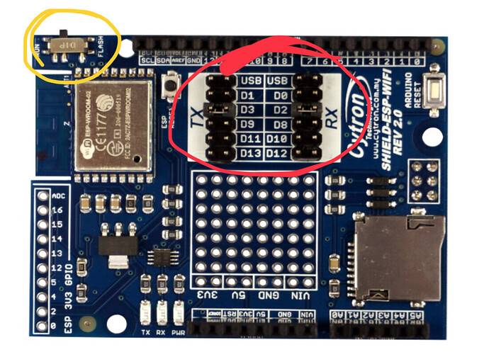
Question 1 relates to the jumpers circled in red on the image below.

Question 2 relates to the switch circled in yellow on the image below.

The user manual is linked from the GitHub page for the shield’s library…

I didn’t say that you need to update the firmware or issue any AT commands, I asked if you had done either of these.

If your DHT sensor is connected to pun 6 then why are you telling your device that it’s connected to pin 2 ?

Your sketch seems to be a mix of Edgent, non-Edgent and NCP sketches.
If you haven’t flashed your ESP with the NCP firmware (which you say you haven’t) then you need to remove the NCP code.

Your device combination doesn’t support Blynk Edgent, so you should remove that code.

The pins used to communicate with the ESP chip are controlled via the jumpers (circled in red) and the baud rate used for communication will depend on the firmware defaults for your shield and any AT commands you’ve issued. The default baud rate is 9600 according to the documentation, not 38400 as you’ve specified in your sketch.

You don’t need to use the Cytron libraries in your sketch.

I’d always recommend using relays with opto isolation to protect your board.

Is there any reason why you’ve chosen the Uno and this WiFi shield instead of a NodeMCU or ESP32 dev board?

Pete.

Hello,

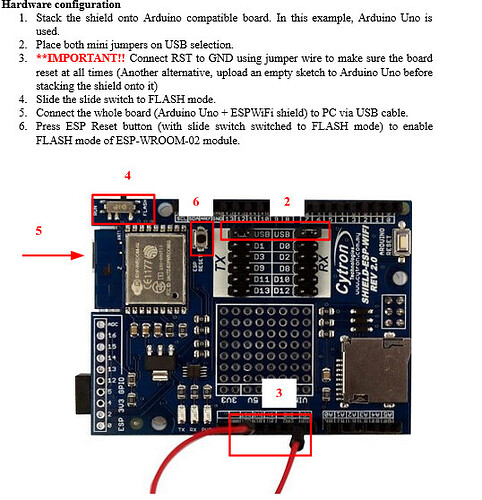
  1. In my project, I have connect jumper on the USB as it was indicated in the guide.
  2. On the shield, the switch is in run position as in the photo.
    3.I followed the firmware installation instructions in the guide (page 14). Do I need to follow the firmware update instructions as well?
  3. For the DHT sensor, it is a mistake on my part. thanks for pointing this out to me.
    I corrected for the baud rate. I removed the Edgent code but Ok for the relay module.
    I chose the Uno board because I already had one when I started my project. Then I looked for a shield compatible with the Uno board and so I found this shield. In addition, I wanted to make a prototype and so I didn’t want to invest in boards that were too expensive although they are becoming less and less expensive.
    I don’t really understand what the NCP code is because I’m a beginner. Which lines are affected?

Another question, when I received the components, they were in a gray plastic bag. I think it’s because of the waves. Is that right?

Thanks

That isn’t the correct setting if you want to use the ESP8266 as a WiFi modem for your Uno.

I specifically said…

I now have no idea how your ESP8266 module is now configured.

You said you were using the Blynk NCP library in one of your earlier posts.

You’ve spent far more on your WiFi shield than an ESP32 dev board would have cost.

I have no idea what your code looks like now, or what sort of compilation errors you are now getting - if any.

Pete.

You didn’t answer my question about the covers.

Another question, when I received the components, they were in a gray plastic bag. I think it’s because of the waves. Is that right?

I did steps 1-4 of the setup as instructed in the guide, which states that for the example it is using an Arduino Uno board.


Apart from these settings on the shield, I haven’t touched anything.

I didn’t say you need to update the firmware or issue AT commands, I asked if you have done either of those.

I do neither.

You’ve spent far more on your WiFi shield than an ESP32 dev board would have cost.

I know but I didn’t want to complicate things for myself.

I don’t know where the NCP code lines are.

Here is my code. Just tell me, if you have time, what’s wrong and how I can fix it. On some lines, I put question marks because I think that is the one that poses a problem.

#define BLYNK_TEMPLATE_ID "Template ID"  
#define BLYNK_TEMPLATE_NAME "Name"   
#define BLYNK_AUTH_TOKEN ""                       //??
#define BLYNK_PRINT Serial                       //??
#define BLYNK_FIRMWARE_VERSION        "0.1.0"   //??
#define BLYNK_PRINT Serial                     //??
#define BLYNK_DEBUG                           //??
#define APP_DEBUG                            //??
#define DHT11_PIN 6                        
#include <ESP8266_Lib.h>  
#include <ESP8266_Lib.h>
#include <BlynkSimpleShieldEsp8266.h>                                     
#include <BlynkRpcClient.h>         //??             
#include <Blynk.h>                               
#include <SoftwareSerial.h>    //??                                 
#include "DHT.h"                                 
char ssid[] = "ssid";                   
char pass[] = "pass";  
int Relaispin = 7;                               
const int seuilHumidite = 400;                   
DHT dht(6, DHT11);                               
SoftwareSerial EspSerial(2, 3);  
#define ESP8266_BAUD 9600;       
ESP8266 wifi(&EspSerial);

void setup() {                                                      
 pinMode(DHT11, INPUT);       
 pinMode(Relaispin, OUTPUT);  
 pinMode(Relaispin, Low);
 digitalWrite(DHT11, LOW);    
  { Serial.begin(115200); //??
    EspSerial.begin(ESP8266_BAUD);  
    delay(10); //??
    Blynk.begin(BLYNK_AUTH_TOKEN, wifi, ssid, pass);  // On peut également spécifier le serveur :       //??
                                                      //Blynk.begin(BLYNK_AUTH_TOKEN, wifi, ssid, pass, "blynk.cloud", 80);
                                                      //Blynk.begin(BLYNK_AUTH_TOKEN, wifi, ssid, pass, IPAddress(192,168,1,100), 8080);
  } { Serial.begin(115200);             //???
  } BLYNK_WRITE(V0) { // Executes when the value of virtual pin 0 changes 
  if (param.asInt() == 1) {
    digitalWrite(7, HIGH); // Set digital pin 2 HIGH // execute this code if the switch widget is now ON
  } else {
    // execute this code if the switch widget is now OFF
    digitalWrite(7, LOW); // Set digital pin 2 LOW
  }
 }
}

void loop() {  //Ce qui se répette tout le temps

  Blynk.run();
  digitalWrite(DHT11, HIGH);
  float h = dht.readHumidity();     
  float t = dht.readTemperature();  

  Serial.print("Humidite: ");                
  Serial.println(h);                      
  Serial.print("Temperature: ");      
  Serial.println(t);                            
  delay(90000);                         // Attendre 90 secondes soit 1 min et  30 s

  int valeurHumidite = analogRead(DHT11);  
  if (valeurHumidite < seuilHumidite) {                             
   digitalWrite(Relaispin, HIGH);                              
   Serial.println("Pompe allumée. Arrosage en cours...");      
    } else {                                                      
       digitalWrite(Relaispin, LOW);                               
       Serial.println("Pompe éteinte.");                           
      }
}

I compiled the program and I have a first mistake:

Compilation error: expected ')' before ';' token

It is on the lign 23.

After, I ad ‘)’ and I discover an other mistake lign 32:

Compilation error: expected primary-expression before ')' token

Thank you for your help

Here is the error message:

In function 'void setup()': sketch_sep1a.ino:32:33: error: expected primary-expression before ')' token
     EspSerial.begin(ESP8266_BAUD);
                                 ^
sketch_sep1a.ino:38:21: error: a function-definition is not allowed here before '{' token
   } BLYNK_WRITE(V0) {  // Executes when the value of virtual pin 0 changes
                     ^

exit status 1

Compilation error: expected primary-expression before ')' token

Thanks

Presumably that was just an anti static bag, to protect the board during transit.

Delete these lines of code.

Presumably, your compiler error messages are because you have an opening curly bracket at the beginning of this line…

Which shouldn’t be there.

You also have two Serial.begin statements when you should only have one, and a function inside a function - BLYNK_WRITE(V0) is a function, and void loop() is also a function. You can’t have one inside another.

I’d suggest that you move your opening curly brackets to a new line, and indent the following code so that you can see what’s happening, like this…

BLYNK_WRITE(V0)  // Executes when the value of virtual pin 0 changes 
{
  if (param.asInt() == 1)
   {
      digitalWrite(7, HIGH); // Set digital pin 2 HIGH // execute this code if the switch widget is now ON
   }
  else 
  {
     // execute this code if the switch widget is now OFF
     digitalWrite(7, LOW); // Set digital pin 2 LOW
  }
}

You can use the IDE to automatically format your code with indents, I can’t remember which menu that command is in, and I’m not in front of a computer at the moment, but I’m sure you’ll find it it you look.

Pete.

Hello,
I have followed your recommendations.
For the relay module, if I put it in anti static bag, it is good ?

You can use the IDE to automatically format your code with indents, I can’t remember which menu that command is in, and I’m not in front of a computer at the moment, but I’m sure you’ll find it it you look.

I’ll look this afternoon.
Thank you for your help.

The static bag is for shipping. Throw it away.

Pete.

Ok for the relay module. When I compil the code, I have this error message:
What I can do ?

C:\Users\Sophie Moreau\Documents\Arduino\sketch_sep1a\sketch_sep1a.ino:19:1: error: 'SoftwareSerial' does not name a type; did you mean 'HardwareSerial'?
 SoftwareSerial EspSerial(2, 3);
 ^~~~~~~~~~~~~~
 HardwareSerial
C:\Users\Sophie Moreau\Documents\Arduino\sketch_sep1a\sketch_sep1a.ino:21:15: error: 'EspSerial' was not declared in this scope
 ESP8266 wifi(&EspSerial);
               ^~~~~~~~~
C:\Users\Sophie Moreau\Documents\Arduino\sketch_sep1a\sketch_sep1a.ino:21:15: note: suggested alternative: 'Serial'
 ESP8266 wifi(&EspSerial);
               ^~~~~~~~~
               Serial
C:\Users\Sophie Moreau\Documents\Arduino\sketch_sep1a\sketch_sep1a.ino: In function 'void setup()':
C:\Users\Sophie Moreau\Documents\Arduino\sketch_sep1a\sketch_sep1a.ino:30:5: error: 'EspSerial' was not declared in this scope
     EspSerial.begin(ESP8266_BAUD);
     ^~~~~~~~~
C:\Users\Sophie Moreau\Documents\Arduino\sketch_sep1a\sketch_sep1a.ino:30:5: note: suggested alternative: 'Serial'
     EspSerial.begin(ESP8266_BAUD);
     ^~~~~~~~~
     Serial
C:\Users\Sophie Moreau\Documents\Arduino\sketch_sep1a\sketch_sep1a.ino:30:33: error: expected primary-expression before ')' token
     EspSerial.begin(ESP8266_BAUD);
                                 ^

exit status 1

Compilation error: 'SoftwareSerial' does not name a type; did you mean 'HardwareSerial'?

thank you for you help.

What version of the SoftwareSerial library do you have installed?

Pete.

it is the Software reset librairy on 3.0.1 version by Guiseppe Masino.
I also did the auto format.
Thank you

My mistake, I’d forgotten that you were using the Uno rather than the Maga.
You need to add this line back in…

#include <SoftwareSerial.h>

Pete.

I have included the librairy. It works
But I have one last mistake:

Compilation error: expected primary-expression before ')' token

About the line :

Serial.begin(115200);
    EspSerial.begin(ESP8266_BAUD); //this line
    delay(10);                                        //??
    Blynk.begin(BLYNK_AUTH_TOKEN, wifi, ssid, pass);  // On peut également spécifier le serveur :       //??
                                                      //Blynk.begin(BLYNK_AUTH_TOKEN, wifi, ssid, pass, "blynk.cloud", 80);
                                                      //Blynk.begin(BLYNK_AUTH_TOKEN, wifi, ssid, pass, IPAddress(192,168,1,100), 8080);

Thank you very much for your help

Some clues about which line this relates to would help, and you need to post the full sketch and full error message.

Pete.