@kaushika_disz Please edit your post, using the pencil icon at the bottom, and add triple backticks at the beginning and end of your code so that it displays correctly.
Triple backticks look like this:
```
Copy and paste these if you can’t find the correct symbol on your keyboard.
I am attempting to use Blynk IoT,
No, I haven’t tried a simple sketch, I need to get the GPS real time location on the Blynk IoT (Lattitude, Longitude, Speed and the Map widget)
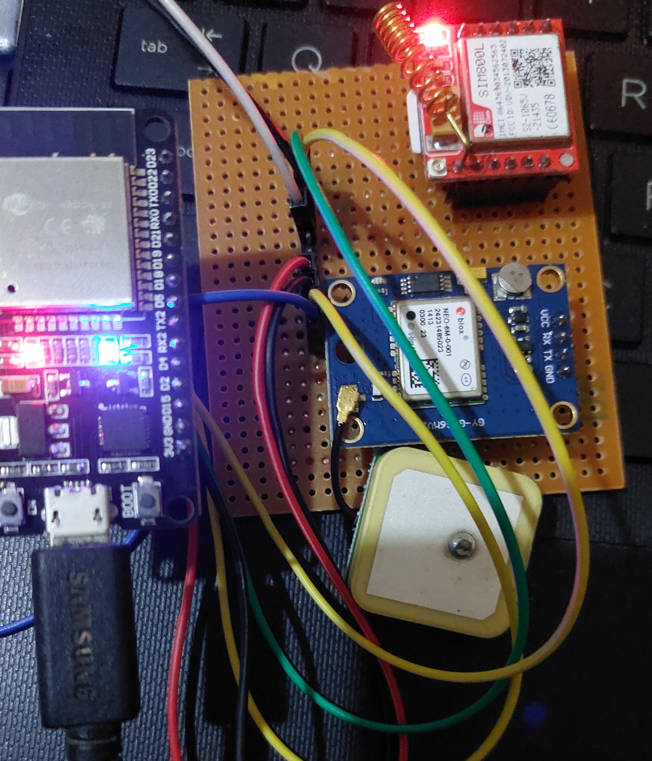
I have connected the 3.3V pin of the ESP32 to the SIM800 module.
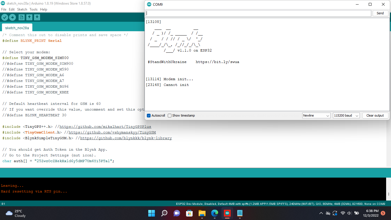
In that case you4 sketch is missing the template ID and device name from the very top of the code.
You need to begin my getting your SIM800 to initialise, and a simple sketch is the simplest way to get get that part working.
That’s almost certainly a bad idea.
The SIM800 module requires a lot of current (around 2A when transmitting data) and the ESP32’s voltage regulator isn’t built to do that.
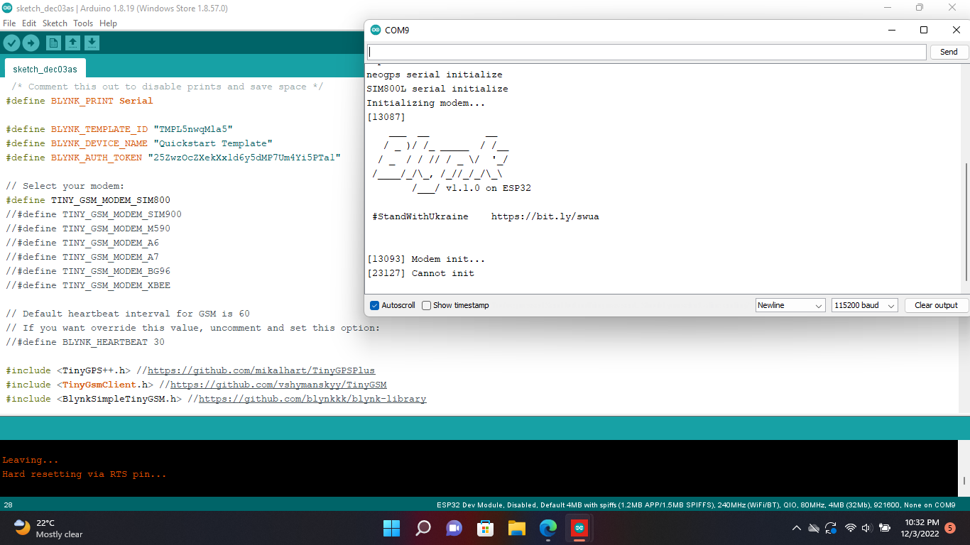
I used a 3.7V battery for the power supply of the SIM800 and i have connected the 3.3V pin for the NEO6M GPS module and the data cable connected properly, and I included the template ID and the device name but still the same error after uploading the code.
void setup() {
Serial.begin(9600);
Serial2.begin(9600);
delay(3000);
test_sim800_module();
send_SMS();
}
void loop() {
updateSerial();
}
void test_sim800_module()
{
Serial2.println("AT");
updateSerial();
Serial.println();
Serial2.println("AT+CSQ");
updateSerial();
Serial2.println("AT+CCID");
updateSerial();
Serial2.println("AT+CREG?");
updateSerial();
Serial2.println("ATI");
updateSerial();
Serial2.println("AT+CBC");
updateSerial();
}
void updateSerial()
{
delay(500);
while (Serial.available())
{
Serial2.write(Serial.read());//Forward what Serial received to Software Serial Port
}
while (Serial2.available())
{
Serial.write(Serial2.read());//Forward what Software Serial received to Serial Port
}
}
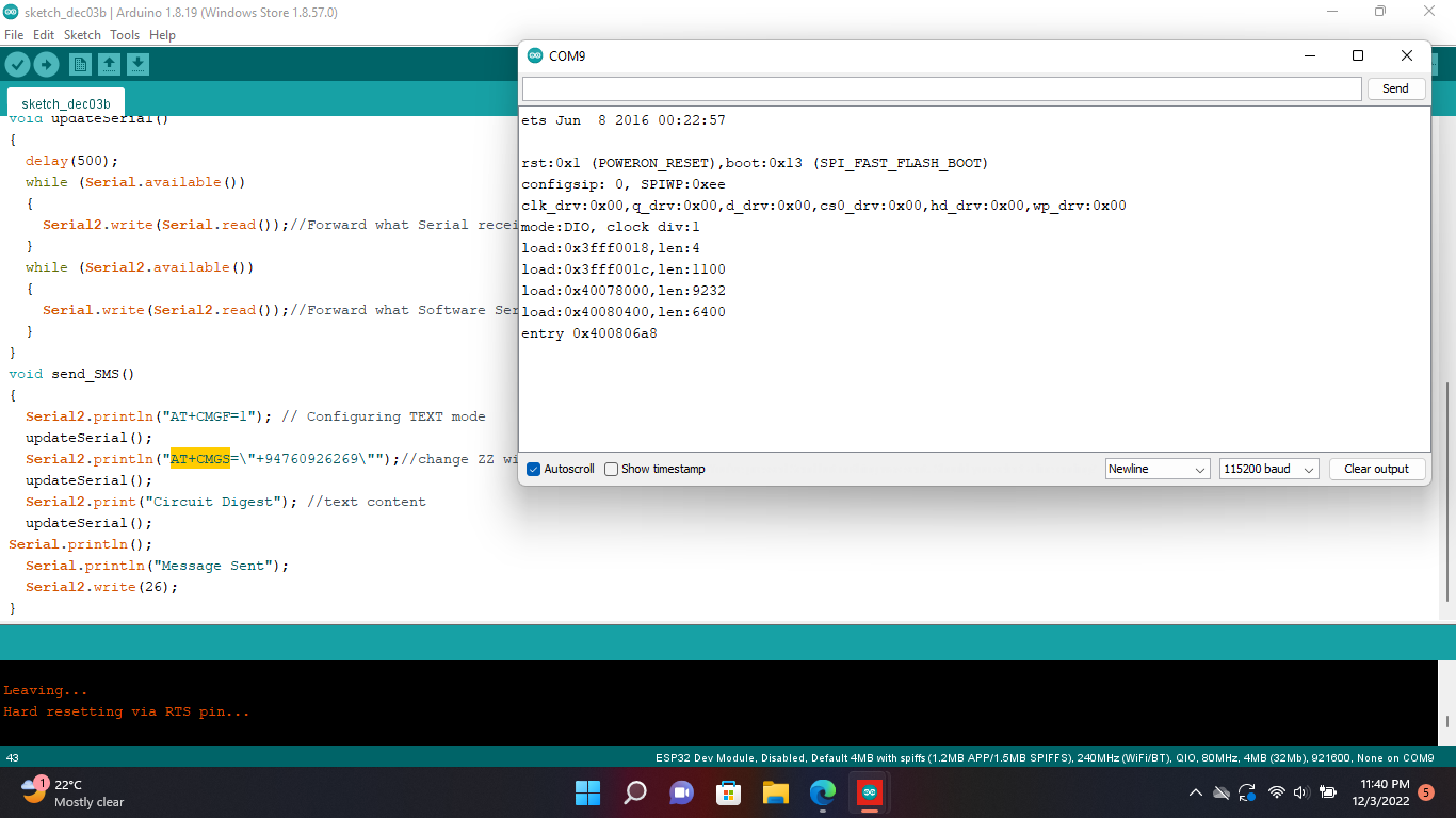
void send_SMS()
{
Serial2.println("AT+CMGF=1"); // Configuring TEXT mode
updateSerial();
Serial2.println("AT+CMGS=\"+94760926269\"");//change ZZ with country code and xxxxxxxxxxx with phone number to sms
updateSerial();
Serial2.print("Circuit Digest"); //text content
updateSerial();
Serial.println();
Serial.println("Message Sent");
Serial2.write(26);
}
I used this code with the ESP32 and the sim 800l and it doesn’t work
I have used the 3.7V battery for the SIM800 and the power supply of the USB port to the ESP32, only the data pins of the SIM800 are connected with the ESP32.
That doesn’t look like any of the TinyGSM examples from the GitHub page to me, and it looks like half a sketch.
It really would help if you copied/pasted the serial monitor output text between triple backticks rather than posting screenshots.
So I guess that means you don’t have a common GND between the two power supplies then? If that’s the case then it won’t work, as the data signals are all relative to the GND reference, and if the grounds are not connected across the two boards then the data signals will mean nothing to the ESP32.