Gate opener remote switch ESP-07 and external antenna

Thought I would share my experiences here so others have less pain and frankly so I can come back here when I have to build another one. App side is stupid simple but the rest is a bit more involved. I have not included code as it should be obvious. Please let me know if you have questions.

So I have a Liftmaster residential gate opener on the edge of my property. It is a good 300’ from the closest place I could place a WAP. It is has solar and house power for winter but no ethernet.

First I setup a NodeMCU board with it’s built in antenna and used a generic blynk led app to activate a 3.3v relay rather than a light. Plan was to use the relay to trip the gate opening circuit which is a simple momentary switch.

Relay off ebay. https://www.ebay.com/itm/4pcs-3V-3-3V-Relay-High-Level-Driver-Module-optocouple-Relay-Module-for-Arduino/362178942607?_trkparms=pageci%3Adf09cbe8-2188-11e8-b0bf-74dbd1803cd4|parentrq%3Afd4e87421610a861b345d21dffff39f6|iid%3A1&_trksid=p2481888.c100675.m4236

NodeMCU
This was an adventure but once learned it is a very easy device to program.

Great instructable. http://www.instructables.com/id/Simple-Led-Control-With-Blynk-and-NodeMCU-Esp8266-/

Buy here: https://www.amazon.com/pack-ESP8266-microcontroller-NodeMCU-CH340G/dp/B071YPS666/ref=sr_1_7?ie=UTF8&qid=1520373390&sr=8-7&keywords=NodeMCU&dpID=61RXqgTSA5L&preST=SY300_QL70&dpSrc=srch

Problem was that it does not have much range and had intermittent wireless connectivity. It worked most of the time.

That is when I had the idea of the ESP-07 and a separate antenna,

Amazon ESP-07 https://www.amazon.com/MagiDeal-ESP8266-Esp-07-Remote-Transceiver/dp/B01C2I7E7E
Amazon Mounting plate https://www.amazon.com/gp/product/B01NCQFSEG/ref=oh_aui_detailpage_o09_s00?ie=UTF8&psc=1

Soldering the board to the plate is simple if fiddly (use flux) and should not need much explanation and there are videos out there. In my case I installed the headers upside down which turned out ok for me.

For setting up the board you will need a serial connector…

Amazon. https://www.amazon.com/gp/product/B00XDLS1UO/ref=oh_aui_detailpage_o08_s00?ie=UTF8&psc=1

WARNING. I could not get a driver to work with this in Win10 but it works out of the box with a Mac. I read somewhere that older windows drivers work with it. You might want to find one that has decent drivers if you have the Windows religion.

This site was invaluable for sussing out how to load code and takes you through how to interface with the board pretty well. http://ediy.com.my/blog/item/133-upload-sketch-to-the-esp8266-esp-07-esp-12-using-arduino-ide

WARNING. There , for me, was not enough power via the 3.3v pin on the serial adaptor to power the serial device and the chip with the serial adaptor alone and it did not work until I added a separate power supply for the board. Sounds obvious but it took me a while to figure out that issue.

Amazon : https://www.amazon.com/gp/product/B010UJFVTU/ref=oh_aui_detailpage_o06_s00?ie=UTF8&psc=1

OK programming is finicky until you get it down. Key is sequence and the fact that you have to ground GPI0 before the board will accept the code…

THIS WORKS!
On the IDE side, I have set the communications parameters to 115200 baud, 8 bits, 1 stop bit, no parity bit, no handshaking, and the appropriate serial port. The sequence I used to program the ESP8266 is:

  1. Apply the external power supply to the ESP8266
  2. Connect a USB cable between the USB-UART and the laptop’s USB port. NOTE: I have to run my laptop on AC power for its USB port to provide sufficent current to the USB-UART.
  3. Ground the GPIO0 pin
  4. Momentarily ground the RST pin
  5. Click the IDE’s upload button

All of this worked to get he app working and hooked to a momentary button in my blynk app. I worked fine 10’ from my router.

WARNING

Do not buy this POS antenna. It will lead to tears…

Spend.a few more bucks and get a one of the many decent add-on 2.4ghz antennas out there… you will also need these connectors.

Amazon: U.FL Mini PCI to RP-SMA Pigtail https://www.amazon.com/gp/product/B005UWD0EG/ref=oh_aui_detailpage_o01_s01?ie=UTF8&psc=1

I say all this about the antenna because I nearly abandoned this project thinking that the board was not that good and besides the NodeMCU was working mostly.

I went down this rabbit hole…
http://www.esp8266.com/viewtopic.php?f=6&t=1550&start=12

In summary the ESP-07 has a little tiny ceramic antenna on it that some say reduces the efficacy of the external antenna. There is microscopic resistor connecting the internal and external that I removed to no avail. Because the antenna I bought was a POS… This was more pain. As soon as i hooked up a regular antenna from an old router everything changed. I have no idea if removing the resistor does anything. I could stick a blob of solder on and reconnect it but maybe someone else can study this.

This video is actually interesting and was part of what got me motivated. Swiss guy comparing internal and external antennae.

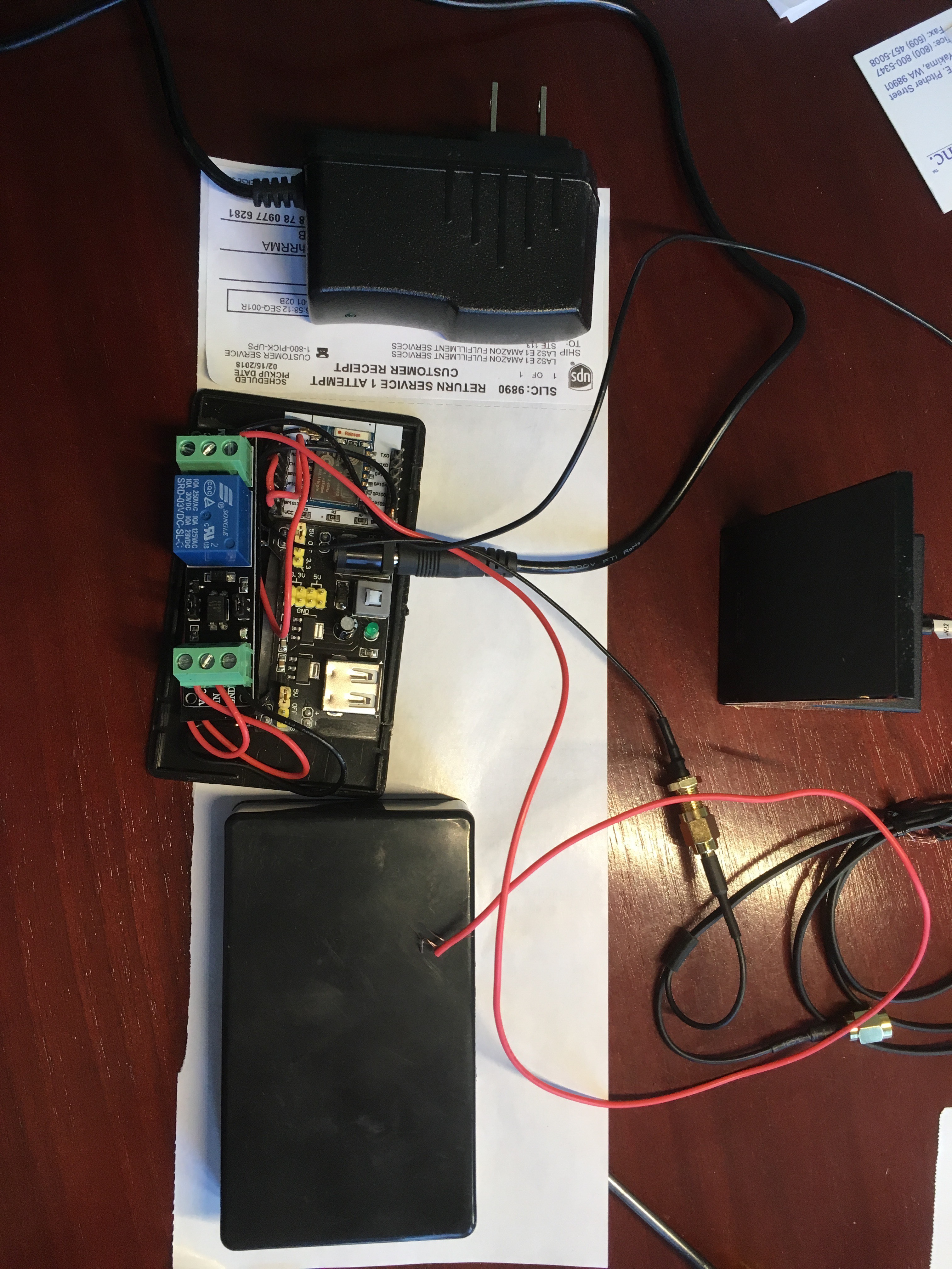
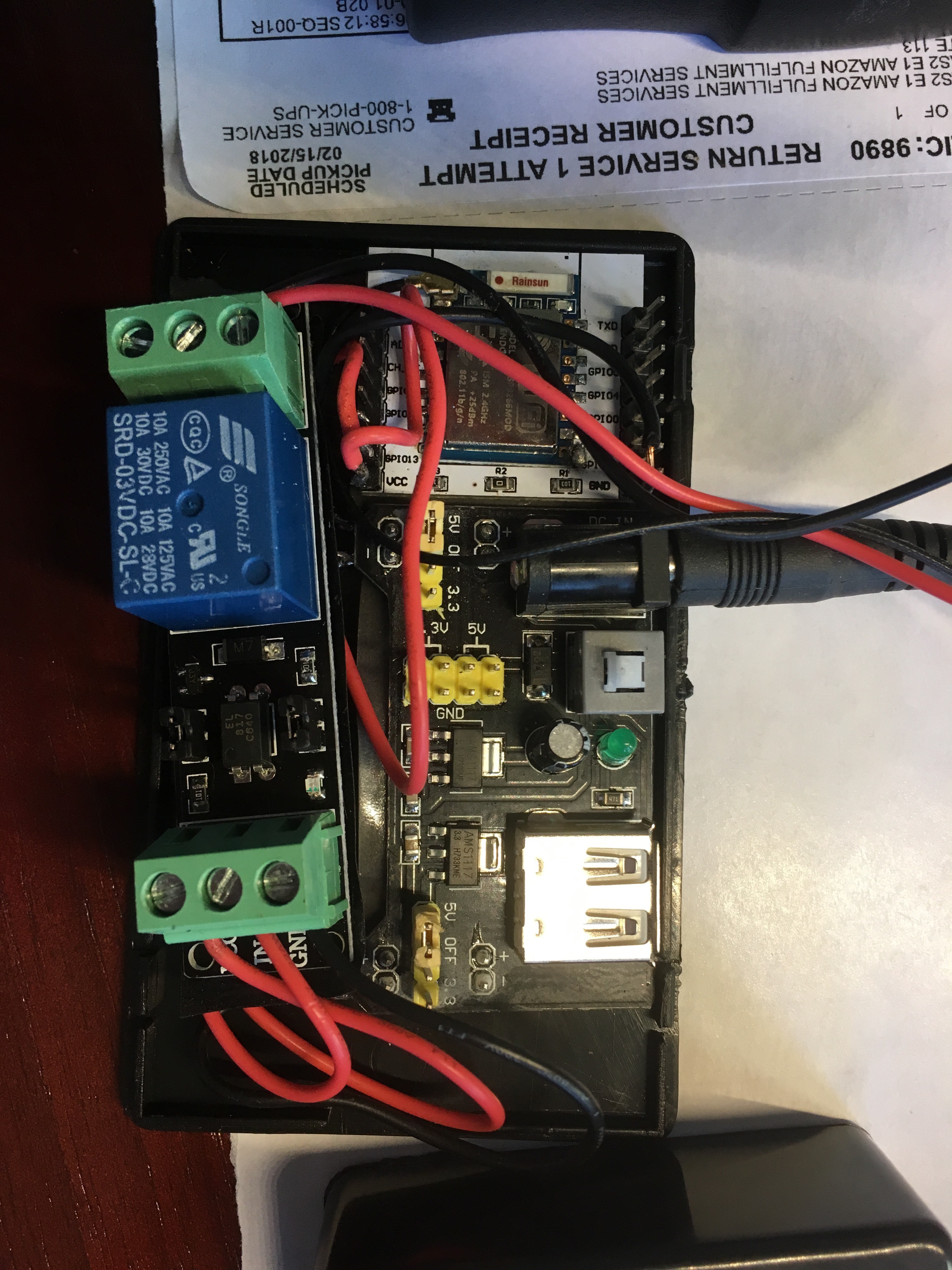
Works like a champ! I can now open my gate from anywhere on the planet. I have all sorts of ideas on other long range battery operated sensors and switches around the property that can use this setup. As I said at very least I hope I can save someone else some hours. I originally put all this on a board but decided to just doubleside tape the components into a little project box.

.

@nickguy, Have you seen these:
Wemos D1 Mini Pro

They have the serial connector built in, and the hook-up for the external antenna. Also, when loading programs from the Arduino IDE there is no need to ground GPIO0.

This might make your next project a little easier.

EDIT: I forgot to mention that they even have shields that can make things even easier.
Wemos Shields

2 Likes

I have now and yes that makes things a LOT simpler. Thanks very much. Another good reason to post the project.

Any advice on disabling the ceramic antenna? It looks like you remove the 0 ohm resistor

Correct.

I thought you were supposed to rotate the resistor by 90°, so that the PCB track is electrically connected to the external socket rather than the ceramic aerial.

Pete.

Don’t think so. I just smacked my 0 ohms with a hammer, literally, until it came off. Actually a sharp pointed “podger” smacked with a hammer.

:rofl::rofl::rofl: :hammer:

Yes, you DO need to do this :smiley: Even just a solder blob will do… in case someone has already gotten near your 0 ohm resistor collection :hammer:

2 Likes

I know you don’t like soldering, but that’s taking things to extremes!

You should watch this video:

then try putting a blob of solder across the track to link the external antenna and see what improvement in signal strength you get. In theory, it should be a significant gain as your external antenna isn’t currently connected to anything.

Pete.

1 Like

My video was much more entertaining… even if I do say so myself :stuck_out_tongue:

I think when the Pro came out the ‘net said smack it wi’ 'ammer, so I did.

I have maybe 5 or 6 Pro’s but I don’t really use them, plain Mini for me.

When I got them I did wander up the street with one, after using the hammer, and signal was pretty good.
Not the 232km world record, or whatever it is, but good enough unless you live in Buck House.

1 Like

I used to “wok daan ‘t pit”, so “‘itin it wi big ‘ammer” was the first step in any fault-finding workflow. I’m just not sure it’s the way to go in this case :wink:

Pete.

1 Like

You’ll know my 2 bruv’s then?

1 Like

They were actually both Miners until the Strike and then one never went back and didn’t speak to the other one for years. AFAIK one bruv is still daan 't pit.

Sadly, there are no deep mines left in the UK now, and no coal-fired power stations either. There are still a few opencast mines I think, mostly in Scotland.
I was a photographer in the midlands until the late 80’s. There’s a few random photos on my website:
http://www.peteknightphotography.com/p289764754

Apologies for dragging @nickguy’s excellent project massively off-topic, but on the bright side it does keep it at the top of the recent posts list😀

I have a similar project at our holiday home on Spain that uses an RFID reader to release a gate lock, alongside an existing door entry system.
It’s currently a stand-alone system that uses an Arduino Mini (runs off to bathroom to wash mouth out with soap), but I have a working prototype of my next upgrade which adds Blynk and 433MHz remote control. I’ll be using a Wemos D1 Pro with a small external aerial, after carefully finessing the zero ohm resistor into its new position using a very fine soldering hammer.
I’ll post some pictures and details when it’s finished.

Pete.

2 Likes

Love the posts. In my case I also used a small sledghammer and the range is great using a decent antenna.

Code that worked for me to enable SmartThings IFTTT integration for momentary button push to trigger the gates’s open sequence.


/* Comment this out to disable prints and save space */
#define BLYNK_PRINT Serial


#include <ESP8266WiFi.h>
#include <BlynkSimpleEsp8266.h>
#include <SimpleTimer.h>
SimpleTimer timer;


// You should get Auth Token in the Blynk App.
// Go to the Project Settings (nut icon).
char auth[] = "blynkcode";

// Your WiFi credentials.
// Set password to "" for open networks.
char ssid[] = "";
char pass[] = "";

void setup()
{
  // Debug console
  
  
  Serial.begin(9600);

  Blynk.begin(auth, ssid, pass);   // You can also specify server:
  
  pinMode(13, OUTPUT);  //pinMode(13, OUTPUT);


  //Blynk.begin(auth, ssid, pass, "blynk-cloud.com", 8442);

  //Blynk.begin(auth, ssid, pass, IPAddress(192,168,1,100), 8442);

}
BLYNK_WRITE(V1) {
   if (param.asInt()==1){  // act only on the HIGH and not the LOW of the momentary
    digitalWrite(13, !digitalRead(13));  // invert pin state just once    timer.setTimeout(2000L, [](){
    timer.setTimeout(2000L, [](){
    digitalWrite(13, !digitalRead(13));  // then invert it back after 2000ms
  Blynk.virtualWrite(V1, LOW);
//    });
  
    });
    }
}
 
  
void loop()
{
  Blynk.run();
  timer.run();
}
1 Like