Hi Blynkers.
The Shelly series, like the Sonoff series of products are flashable with your own firmware. Shelly RGBW 2 is an ESP8266 device with 2MB of memory.
There is plenty of online doc on using the Shelly RGBW 2 and on flashing to other standards, but not much on flashing to Arduino using the Arduino IDE. I use Blynk in my home automation, needed to be able to program the Shelly RGBW 2 myself.
And since it took me a while to figure out how to work it, I share with you.
Thanks to @PeteKnight for his guidance and pointers, especially his blog post
[As simple as it gets | Pete Knight's Tech Blog]
ADVICE and PREP
If you have not yet flashed a Shelly or a Sonoff, yourself, I recommend you get your software generally working with OTA on a more standard ESP8266. It’s just easier until your Shelly is up on OTA and running. I use NodeMCU 1.0 devices to get my Shelly or Sonoff code running, first. Then when it’s pretty stable, I flash the Shelly and go from there using OTA. I rely on TelnetStream to see what the Shelly is doing once disconnected from my computer. (I also use IFTTT for long-term monitoring of my device performance once deployed.)
Buy a USB to TTL Serial Adapter. Set it to 3.3 VDC. I use this one, below. Actually I have two, one is set to 5 VDC, one set to 3.3 VDC. This adapter has treated me well. Here’s a link on Amazon.com US.
[https://www.amazon.com/gp/product/B07BBPX8B8/ref=ppx_yo_dt_b_asin_title_o05_s01?ie=UTF8&psc=1]
SETTING UP
Hardware
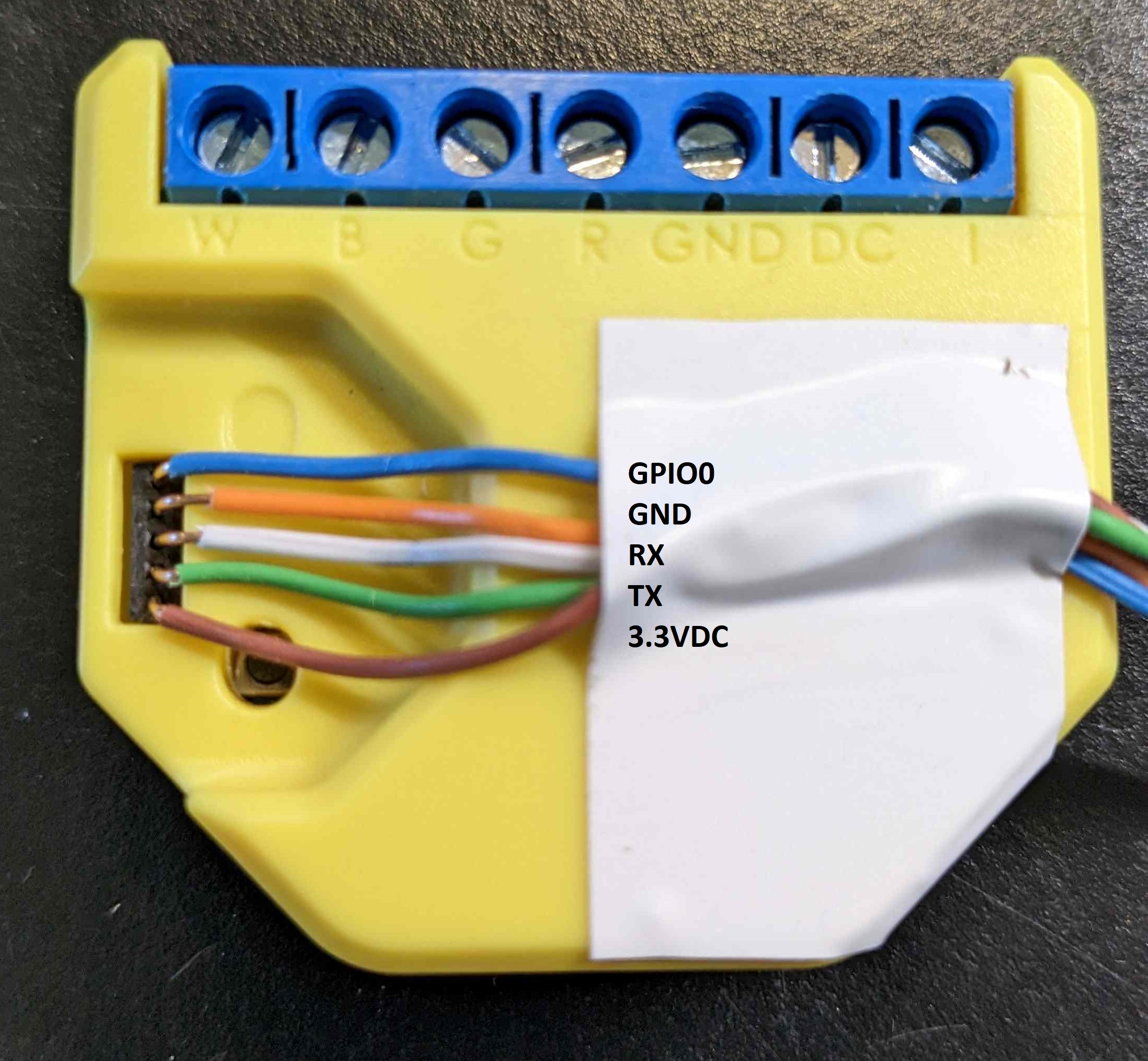
You want your USB to TTL Serial Adapter connected to your Shelly like this.
Connect the 3.3VDC, GND, RX, and TX (reversing RX and TX) to the USB to TTL Serial Adapter.
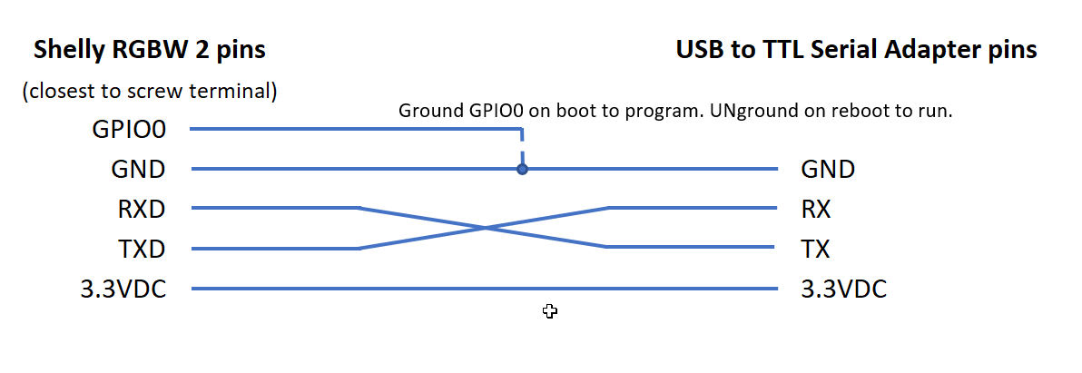
You will need to connect the Shelly GPIO0 to GND to flash the device. I use a small breadboard and an extra wire to connect GPIO0 to GND prior to flashing. When not flashing, the GPIO0 can float free.
I use very thin 22 ga wire found in Cat 5 or 6 cable to insert into the tiny pin sockets since the Shelly RGBW 2 doesn’t have the usual pins exposed.
Code is below.
This sketch is simply to get started. It does not include Blynk, OTA, or IFTTT code to keep it simple. It does include TelnetStream, which I find very helpful. I use PuTTY to see the TelnetStream once the device is connected to WiFi. Once you add OTA, use TelnetStream instead of Serial.print to work without the USB to TTL Adapter.
#define SKETCH_NAME   "SHELLY_RGBW2_TESTBED"     // used in WiFi setup, Blynk and OTA

#define SERIAL_SPEED  230400

//////////////////////////////////////////////////////////////////////////////////////////////////////////////////////

// This simple testbed sets up a non-Blynk-enabled, non-OTA tesbed for Shelly RGBW 2

// Ground GPIO 0 while plugging in device, upload, unground GPIO 0 and reboot by unplugging

//

// REMEMBER to not have Shelly RGBW 2 connectedt ot your computer while powering the Shelly with 12 or 24 VDC

// Use Telnet to see what Shelly is up to while powered by 12 VDC or 24 VDC (I like PuTTY for Telnet)

//

// BUTTON GPIO shows button status

// LED GPIO turns LED on and off.

//////////////////////////////////////////////////////////////////////////////////////////////////////////////////////

/////////////////// April 2023

/*

 * I find the Shelly RGBW 2 has enough memory to use

 * - Blynk,

 * - OTA,

 * - IFTTT,

 * - Serial communications,

 * - TelnetStream, and

 * - HTTP get and update calls to Blynk Datastreams on other devices

 *

 * and still have a reasonably robust sketch.

 *

 * I use BLYNK_WRITE ( VPIN ) to get commands from other devices

 */

/*

Arduino IDE Settings

- Board: Generic ESP8266 MOdule

- Any 2MB setting. I used (FS: 265KB OTA~869KB) for this sketch

- Upload speed 256000

- Serial Monitor (Serial.begin() speed 230400)

*/

//////////////////////////////////////////////////////////////////////////////////////////////////////////////////////

// Define the pins on the Shelly RBGW 2

//////////////////////////////////////////////////////////////////////////////////////////////////////////////////////

// See Pete Knight's Tech Blog https://peteknight.webador.co.uk/859087_as-simple-as-it-gets

//  for good doc and a terrific idea for flashing these things at scale

//////////////////////////////////////////////////////////////////////////////////////////////////////////////////////

#define PWM1_GPIO                 12 // Red output

#define PWM2_GPIO                 15 // Green output

#define PWM3_GPIO                 14 // Blue output

#define PWM4_GPIO                 4  // White output

#define SHELLY_CURRENT_METER_PIN  A0 // Coarse analog current meter

#define SHELLY_USER_PIN           5  // INPUT_PULLUP - sees "I" to Ground screw terminals on device

#define SHELLY_BUTTON_PIN         13 // LOW when pressed

#define SHELLY_ONBOARD_LED        2  // LOW = ON (typical ESP8266 reversed LED)

// #defines MY_WIFI_SSID, ..2, ..3 AND MY_WIFI_PASSWORD. ..2, ..3 series for WiFiMUlti

#include "MY_WIFI_CREDENTIALS.h"     // I put this in my .library folder

/* for example, MY_WIFI_CREDENTIALS.h library file might look like this...

#define MY_WIFI_SSID "MyOwnWiFiSSID"                  // network SSID (name)

#define MY_WIFI_PASSWORD "hey-this is secreet 9897%%& // network password

#define MY_WIFI_SSID2 "Virus-Vault"                   // network SSID (name)

#define MY_WIFI_PASSWORD2 "TwoFourSixEight2468!"      // network password

#define MY_WIFI_SSID3 "MyAndroidPhone"                // network SSID (name)

#define MY_WIFI_PASSWORD3 "AndroidPassword66$"        // network password

*/

#include <ESP8266WiFiMulti.h>           // WiFi library for ESP8266

ESP8266WiFiMulti wifiMulti;             // set up the WiFi object

const uint32_t connectTimeoutMs = 8000; // timing for WiFiMulti testing connection

// Use Telnet to watch devices like the Shellys when they're disconnected.

// Telnet is included in this sketch, requiring WiFi

#include <TelnetStream.h>

time_t lastReadingTime;  // void loop uses this as a simple timer


//////////////////////////////////////////////////////////////////////////////////////////////////////////////////////

//////////////////////////////////////////////////////////////////////////////////////////////////////////////////////

//////////////////////////////////////////////////////////////////////////////////////////////////////////////////////

// SETUP WIFI, BLYNK, HEARTBEAT, ANYTHING ELSE THAT NEEEDS TO BE SET UP                                             //

//////////////////////////////////////////////////////////////////////////////////////////////////////////////////////

void setup()

{

  delay ( 2000 );

  Serial.begin ( SERIAL_SPEED );

  delay ( 2500 );

  Serial.println ( "\n\n======================================= " ); Serial.println ( SKETCH_NAME );

  pinMode ( SHELLY_ONBOARD_LED, OUTPUT );       // LOW -> turn LED OFF (RGBW 2 LED is too dim to be useful)

  for ( int i = 0; i < 10; i++ )

  {

    digitalWrite ( SHELLY_ONBOARD_LED, 0 );

    delay ( 500 );

    Serial.print ( ">> " );

    digitalWrite ( SHELLY_ONBOARD_LED, 1 );

    delay ( 500 );

  }

  // Set up the four color output PWM pins on the Shelly TGBW 2

  pinMode ( PWM1_GPIO, OUTPUT ); // RED

  pinMode ( PWM2_GPIO, OUTPUT ); // GREEN

  pinMode ( PWM3_GPIO, OUTPUT ); // BLUE

  pinMode ( PWM4_GPIO, OUTPUT ); // WHITE

  // Walk through each light at dim

  for ( int repeat = 1; repeat <= 3; repeat++ )

  {

    setLightLevels ( 50,  0,  0,  0 );

    delay ( 200 );

    setLightLevels (  0, 50,  0,  0 );

    delay ( 200 );

    setLightLevels (  0,  0, 50,  0 );

    delay ( 200 );

    setLightLevels (  0,  0,  0, 50 );

    delay ( 200 );

  }

  // Turn on all lights (half brightess)

  setLightLevels ( 127, 127, 127, 127 ); // blue up during WiFi connection

  // Set up the rest of the Shelly RGBW 2 pins for reading current, switch position, and button position

  pinMode ( SHELLY_CURRENT_METER_PIN, OUTPUT );       // Current meter (sucks) - must calibrate with known currents

  pinMode ( SHELLY_USER_PIN,          INPUT );        // 0 when "I" not grounded; 1 when "I" grounded

  pinMode ( SHELLY_BUTTON_PIN,        INPUT_PULLUP ); // 1 when NOT pushed; 0 when pushed

  // Connect to WiFi and Blynk

  connectToWLAN();  // Connect to WiFi

  // Only Telnet uses WiFi in this sketch

  TelnetStream.begin();


// Turn off all lights after WiFi connected

  setLightLevels ( 0, 0, 0, 0 );  // back to dark (0-255)

  lastReadingTime = 0;  // Force current meter reading asap in void loop

  Serial.println();

  Serial.println ( "**********************"   );

  Serial.println ( "... Setup complete ..."   );

  Serial.println ( "**********************\n" );

} //end setup


#define READ_SHELLY_PINS_INTERVAL 3000 // Do the read every 3 seconds

int shellyLED = 0;

// KEEPING IT SIMPLE

void loop()

{

  if ( ( millis() - lastReadingTime ) >= READ_SHELLY_PINS_INTERVAL )

  {

    // Read and report on Shelly RGBW 2 current (ammeter), switch position, and button position

    readAndReportOnShellyPins();

    // Change the lighting for this demo

    setLightLevels ( random ( 0, 256 ), random ( 0, 256 ), random ( 0, 256 ), random ( 0, 256 ) );

    // Change state of the lED

    shellyLED = 1 - shellyLED;

    digitalWrite ( SHELLY_ONBOARD_LED, shellyLED );

    // Do this again after a few seconds

    lastReadingTime = millis();

  }

} // end loop


// Slam each LED light string to a certain level 0-255

// Set colorLevel to the new level

void setLightLevels ( int r, int g, int b, int w )

{

  analogWrite ( PWM1_GPIO, r ); // Red = 1


  analogWrite ( PWM2_GPIO, g ); // Green = 2


  analogWrite ( PWM3_GPIO, b ); // Blue = 3

  analogWrite ( PWM4_GPIO, w ); // White = 4

}


void readAndReportOnShellyPins()

{

  // Print to serial

  Serial.println();

  Serial.println ( "Time " + String ( millis() ) );

  Serial.print   ( "  Analog output = " + String ( analogRead ( SHELLY_CURRENT_METER_PIN ) ) );

  Serial.print   ( "  USER_GPIO    " + String ( digitalRead ( SHELLY_USER_PIN ) ) );

  Serial.println ( "  BUTTON1_GPIO " + String ( digitalRead ( SHELLY_BUTTON_PIN ) ) );


  // Send to Telnet

  TelnetStream.println();

  TelnetStream.println ( "Time " + String ( millis() ) );

  TelnetStream.print   ( "  Analog output = " + String ( analogRead ( SHELLY_CURRENT_METER_PIN ) ) );

  TelnetStream.print   ( "  USER_GPIO    " + String ( digitalRead ( SHELLY_USER_PIN ) ) );

  TelnetStream.println ( "  BUTTON1_GPIO " + String ( digitalRead ( SHELLY_BUTTON_PIN ) ) );


} // end readAndReportOnShellyPins


// Connect to MultiWiFi gracefully

// Call in Setup()

// Must #define MY_SSID... and MY_WIFI_PASSWORD... somewhere

// Cloned 20 Feb 2023

void connectToWLAN()

{

  WiFi.persistent ( false ); // Don't save anything in EEPROM or LittleFS

  WiFi.mode ( WIFI_STA );    // Station mode


  // Register THREE multi WiFi networks

  wifiMulti.addAP ( MY_WIFI_SSID,  MY_WIFI_PASSWORD  );

  wifiMulti.addAP ( MY_WIFI_SSID2, MY_WIFI_PASSWORD2 );

  wifiMulti.addAP ( MY_WIFI_SSID3, MY_WIFI_PASSWORD3 );

  int WiFiTries = 0;

  // Test for WiFi connectivity. Reboot after 5 tries.

  while ( wifiMulti.run ( connectTimeoutMs ) != WL_CONNECTED )

  {

    WiFiTries++;

    Serial.print ( "WiFi not connected... #" + String ( WiFiTries ) );


    if ( WiFiTries >= 5 )

    {

      Serial.println ( "RESTARTING!\n\n" );

      delay ( 2000 );

      ESP.restart();

    }

    delay ( 5000 ); // delay is ok for OTA and Blynk prior to WiFi connection

  }


  Serial.print ( "WiFi connected just fine to ");

  Serial.print ( WiFi.SSID() ); Serial.print ( " at " ); Serial.println ( WiFi.localIP() ); // String does not do this well!

  Serial.println();


} // end connectToWLAN
To flash the Shelly RGBW 2
Connect the Shelly RGBW 2 to the USB to TTL Adapter.
Connect the Shelly GPIO0 to GND.
Plug the USB to TTL Adapter into your computer.
Tell Arduino IDE what port you are using. Arduino IDE settings are in the sketch. Shelly RGBW 2 is a Generic ESP8266 Module with 2 MB memory.
Compile and upload.
Unground the GPIO0
Disconnect and reconnect the USB to TTL Adapter.
Turn on Serial Monitor to see what’s going on.
What this code does
void setup()
-
turns on the Shelly,
-
blinks the onboard LED (which you can hardly see)
-
connects to WiFi. I use an #included file which contains Wifi SSIDs and passwords.
-
turns on Telnet
-
shows some light changes on all 4 channels (RGBW)
void loop()
Displays (on Serial and TelnetStream)
-
Simple timestamp
-
Analog value of the current meter. This needs to be calibrated to make it useful.
-
USER_GPIO – value of 0 normally, goes to 1 when the I screw terminal is connected to the GND terminal
-
BUTTON_GPIO – value of 1 normally, goes to 0 when you press the little button
When connected to lights and 12/24VDC (and not to your USB to TTL Adapter)
change the lights display randomly
Changes the onboard LED from o to off or back to on
Now, it’s up to you. There’s plenty of doc on wiring this device to 12VDC or 24VDC and 4 channels of output. Make sure you’ve disconnected the USB to TTL Adapter before connecting the 12VDC or 24VDC.
Once you have your Shelly RGBW 2 running OTA code, you do not need the USB to TTL Serial adapter ever again.
I used my first Shelly RGBW 2 to power RGBW LED strings. I’m now using another Shelly RGBW 2 to drive 4 white LED strips. All using Blynk, Blynk API calls, BLYNK_WRITE (), IFTTT, and TelnetStream.
All comments welcome. Hope this is useful and generally correct.