Hey fellow Blynkers. By the way a huge shout out to the founders for this great software. I am a newbie with Blynk and Arduino in general. I have tried to follow the instructions given on this page: http://www.instructables.com/id/Connect-to-Blynk-using-ESP8266-as-Arduino-Uno-wifi/. While following the steps and trying to flash the ESP8266, I get this following message:
Ashwins-MacBook-Pro:esptool-master ashwinkumar94$ sudo ./esptool.py --port /dev/tty.usbmodemFA131 write_flash 0x00000 AT22SDK10020150320boot12.bin
Password:
Connecting…
A fatal error occurred: Failed to connect to ESP8266
My connections are correct, however I have read somewhere that the UNO might not be able to provide enough current to the ESP8266. Is this giving me the problem? Any help is greatly appreciated. Thank you!!
Possibly yes. I’d recommend a decent external power supply and a little capacitor across the lines to keep it powered correctly.
You may want to invest a decent usb-to-serial device for this sort of things though. It may work with an UNO, but a ftdi chip on your USB port is probably more stable.
No, not really, the Internet is full of stuff about this subject.
The first question of the day is, do you have an ESP at 5v or 3.3v? That makes a difference. You should regulate your ESP with the correct voltage. Placing the capacitor is not difficult, the only thing you need to be VERY aware of is the fact that a capacitor has polarity. That means that you should have the - on ground and the +, well, on plus.
*** If you don’t to that it can explode! ***
You can just put the capacitor directly to the + and - of your ESP, it will act as a sort of short-term battery so there is always an ampel power supply to your ESP.
most of time UNO will not provide enough Power to ESP8266 board in normal operation but in flashing mode it will do.
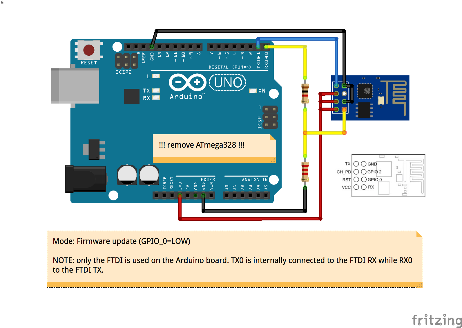
you must have the original UNO or clone that comes with the removable ATMEL chip , as you must remove the chip to allow the serial chip write the sketch directly to the ESP8266 Board.
Uno has 3.3V output but provide only 40 mA and ESP-01 uses between 200-300 mA in operation mode
but flash Mode is less that these but UNO can flash ESP-01 if you removed the chip so serial TX ,RX willl talk directly to ESP-01 not the atmel chip of arduino.
easier buy USB to serial you will need it almost every esp8266 project
Alright I am able to give AT commands in the serial monitor of arduino IDE. But it is still not flashing and giving the same error. Is the problem with the firmware? If so how to achieve this successfully on a Mac? If there are any Windows links it would be appreciated as well
First try setting GPIO-0 to Ground, and tapping (and then removing) RST to Ground and THEN try uploading the firmware. This puts it into a special mode for uploading. If that doesn’t work, try flipping your TX/RX pins around and doing the same thing again.
It helped considerably when I started with the ESP. If you get a decent USB-to-Serial with DTR and RTS pins exposed, you can make an auto-uploader with a small print an tiny capacitor.
Hi I am having the exact same problem as @ashwinkumar1994 as stated in the first post. I am using Arduino Uno with the Sparkfun ESP8266 Wifi Shield. I have a separate “wall wart” power supply so power isn’t my problem, at least I don’t think so (I am quite new to this). I tried removing the chip from the Arduino as mentioned in the thread but I still get the fatal error when uploading. I tried connected GPIO-0 to GND as mentioned and the power and status led’s both blanked out. Is that normal? Im a little lost now, any help would be greatly appreciated. Thanks
@smike I can’t be 100% sure about the LED’s but it is probable that they are ‘blanked out’ when you ground GPIO-0. Grounding GPIO-0 is essential for loading new firmware to the ESP’s so you must do this. As the ESP is then in ‘flashing’ mode then you would expect the LED’s to show a different state to when it is in running / WiFi mode.
I don’t have the Sparkfun WiFi shield so I can’t really help further. Do you not have a USB to Serial/TTL adapter that you could use to flash the ESP?


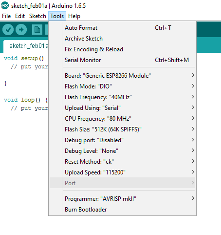
 , you should select the Board type as below