Hardware model + communication type: esp32-cam with wifi
Smartphone OS (iOS or Android) + version: Android 11
Blynk server, Blynk Library version: 0.6.1
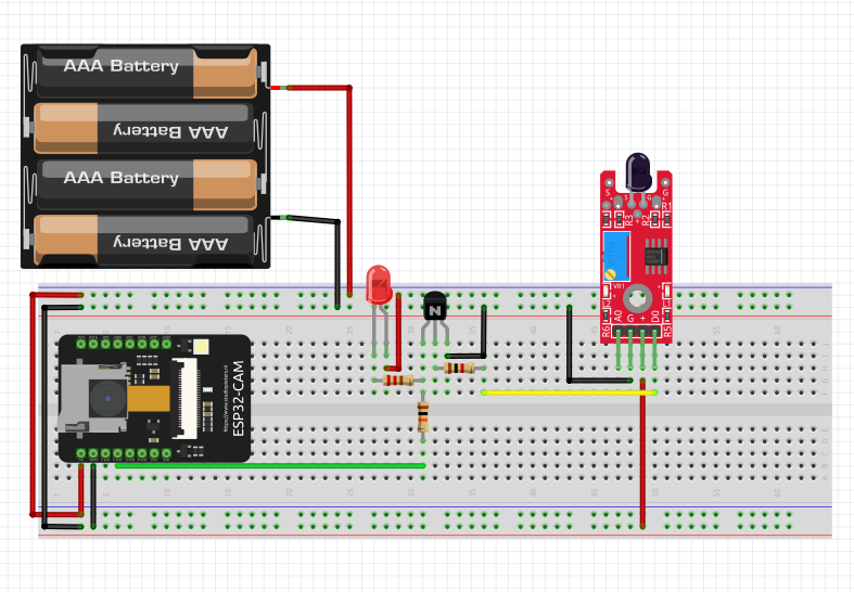
Hi, I’m trying to make a alarm system that when the flame sensor detects the fire, it takes the photo and sends alarm to blynk. It is not working so far but I want to know what part is not working. It would be very helpful if you give me any advice.
Thank you.
#include "esp_camera.h"
#include <WiFi.h>
#include <WiFiClient.h>
#include <BlynkSimpleEsp32.h>
BlynkTimer timer; //

// Select camera model
#define CAMERA_MODEL_AI_THINKER // Has PSRAM

#include "camera_pins.h"

#define FLAME 13
#define PHOTO 14
#define LED 4

const char* ssid = "wifiname";
const char* password = "password";
char auth[] = "0123456789";  //sent by Blynk
int flag=0; //

String local_IP;

void startCameraServer();

void takePhoto()
{
  digitalWrite(LED, HIGH);
  delay(200);
  uint32_t randomNum = random(50000);
  Serial.println("http://"+local_IP+"/capture?_cb="+ (String)randomNum);
  Blynk.setProperty(V1, "urls", "http://"+local_IP+"/capture?_cb="+(String)randomNum);
  digitalWrite(LED, LOW);
  delay(1000);
}

void notifyOnFire() //
{
  int isButtonPressed = digitalRead(FLAME);
  if (isButtonPressed==1 && flag==0) {
    Serial.println("Fire in the House");
    Blynk.notify("Alert : Fire in the House");
    takePhoto();
    flag=1;
  }
  else if (isButtonPressed==0)
  {
    flag=0;
  }
}

void setup() {
  Serial.begin(115200);
  pinMode(LED,OUTPUT);
  pinMode(FLAME,INPUT_PULLUP); //
  timer.setInterval(1000L,notifyOnFire); //
  Serial.setDebugOutput(true);
  Serial.println();

  camera_config_t config;
  config.ledc_channel = LEDC_CHANNEL_0;
  config.ledc_timer = LEDC_TIMER_0;
  config.pin_d0 = Y2_GPIO_NUM;
  config.pin_d1 = Y3_GPIO_NUM;
  config.pin_d2 = Y4_GPIO_NUM;
  config.pin_d3 = Y5_GPIO_NUM;
  config.pin_d4 = Y6_GPIO_NUM;
  config.pin_d5 = Y7_GPIO_NUM;
  config.pin_d6 = Y8_GPIO_NUM;
  config.pin_d7 = Y9_GPIO_NUM;
  config.pin_xclk = XCLK_GPIO_NUM;
  config.pin_pclk = PCLK_GPIO_NUM;
  config.pin_vsync = VSYNC_GPIO_NUM;
  config.pin_href = HREF_GPIO_NUM;
  config.pin_sscb_sda = SIOD_GPIO_NUM;
  config.pin_sscb_scl = SIOC_GPIO_NUM;
  config.pin_pwdn = PWDN_GPIO_NUM;
  config.pin_reset = RESET_GPIO_NUM;
  config.xclk_freq_hz = 20000000;
  config.pixel_format = PIXFORMAT_JPEG;

  if(psramFound()){
    config.frame_size = FRAMESIZE_UXGA;
    config.jpeg_quality = 10;
    config.fb_count = 2;
  } else {
    config.frame_size = FRAMESIZE_SVGA;
    config.jpeg_quality = 12;
    config.fb_count = 1;
  }

  // camera init
  esp_err_t err = esp_camera_init(&config);
  if (err != ESP_OK) {
    Serial.printf("Camera init failed with error 0x%x", err);
    return;
  }

  sensor_t * s = esp_camera_sensor_get();
  // initial sensors are flipped vertically and colors are a bit saturated
  if (s->id.PID == OV3660_PID) {
    s->set_vflip(s, 1); // flip it back
    s->set_brightness(s, 1); // up the brightness just a bit
    s->set_saturation(s, -2); // lower the saturation
  }
  // drop down frame size for higher initial frame rate
  s->set_framesize(s, FRAMESIZE_QVGA);

  WiFi.begin(ssid, password);

  while (WiFi.status() != WL_CONNECTED) {
    delay(500);
    Serial.print(".");
  }
  Serial.println("");
  Serial.println("WiFi connected");

  startCameraServer();

  Serial.print("Camera Ready! Use 'http://");
  Serial.print(WiFi.localIP());
  local_IP = WiFi.localIP().toString();
  Serial.println("' to connect");
  Blynk.begin(auth, ssid, password);
}

void loop() {
  // put your main code here, to run repeatedly:
  Blynk.run();
  timer.run();
  }
I’m not sure how you expect us to know that, asked on the information you’ve provided.
Does the code compile?
Does the device connect to Blynk and show as online?
Can you view the images via the URL?
Which part isn’t working from your perspective?
What widgets wo you have in your app, and which pins are they connected to?
What type of flame sensor?
What is it connected to?
How does it notify your hardware of a fire?
#include "esp_camera.h"
#include <WiFi.h>
#include <WiFiClient.h>
#include <BlynkSimpleEsp32.h>
//
// WARNING!!! PSRAM IC required for UXGA resolution and high JPEG quality
// Ensure ESP32 Wrover Module or other board with PSRAM is selected
// Partial images will be transmitted if image exceeds buffer size
//
// Select camera model
#define CAMERA_MODEL_AI_THINKER // Has PSRAM
#include "camera_pins.h"
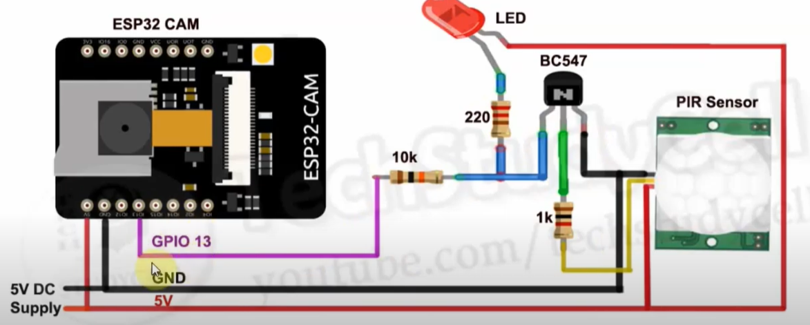
#define PIR 13
#define PHOTO 14
#define LED 4
const char* ssid = "Jang wifi";
const char* password = "94047960";
char auth[] = "Io_v5QZsyr50Pwue9hElEAXaESfFQTkfV"; //sent by Blynk
String local_IP;
void startCameraServer();
void takePhoto()
{
digitalWrite(LED, HIGH);
delay(200);
uint32_t randomNum = random(50000);
Serial.println("http://"+local_IP+"/capture?_cb="+ (String)randomNum);
Blynk.setProperty(V1, "urls", "http://"+local_IP+"/capture?_cb="+(String)randomNum);
digitalWrite(LED, LOW);
delay(1000);
}
void setup() {
Serial.begin(115200);
pinMode(LED,OUTPUT);
Serial.setDebugOutput(true);
Serial.println();
camera_config_t config;
config.ledc_channel = LEDC_CHANNEL_0;
config.ledc_timer = LEDC_TIMER_0;
config.pin_d0 = Y2_GPIO_NUM;
config.pin_d1 = Y3_GPIO_NUM;
config.pin_d2 = Y4_GPIO_NUM;
config.pin_d3 = Y5_GPIO_NUM;
config.pin_d4 = Y6_GPIO_NUM;
config.pin_d5 = Y7_GPIO_NUM;
config.pin_d6 = Y8_GPIO_NUM;
config.pin_d7 = Y9_GPIO_NUM;
config.pin_xclk = XCLK_GPIO_NUM;
config.pin_pclk = PCLK_GPIO_NUM;
config.pin_vsync = VSYNC_GPIO_NUM;
config.pin_href = HREF_GPIO_NUM;
config.pin_sscb_sda = SIOD_GPIO_NUM;
config.pin_sscb_scl = SIOC_GPIO_NUM;
config.pin_pwdn = PWDN_GPIO_NUM;
config.pin_reset = RESET_GPIO_NUM;
config.xclk_freq_hz = 20000000;
config.pixel_format = PIXFORMAT_JPEG;
// if PSRAM IC present, init with UXGA resolution and higher JPEG quality
// for larger pre-allocated frame buffer.
if(psramFound()){
config.frame_size = FRAMESIZE_UXGA;
config.jpeg_quality = 10;
config.fb_count = 2;
} else {
config.frame_size = FRAMESIZE_SVGA;
config.jpeg_quality = 12;
config.fb_count = 1;
}
// camera init
esp_err_t err = esp_camera_init(&config);
if (err != ESP_OK) {
Serial.printf("Camera init failed with error 0x%x", err);
return;
}
sensor_t * s = esp_camera_sensor_get();
// initial sensors are flipped vertically and colors are a bit saturated
if (s->id.PID == OV3660_PID) {
s->set_vflip(s, 1); // flip it back
s->set_brightness(s, 1); // up the brightness just a bit
s->set_saturation(s, -2); // lower the saturation
}
// drop down frame size for higher initial frame rate
s->set_framesize(s, FRAMESIZE_QVGA);
WiFi.begin(ssid, password);
while (WiFi.status() != WL_CONNECTED) {
delay(500);
Serial.print(".");
}
Serial.println("");
Serial.println("WiFi connected");
startCameraServer();
Serial.print("Camera Ready! Use 'http://");
Serial.print(WiFi.localIP());
local_IP = WiFi.localIP().toString();
Serial.println("' to connect");
Blynk.begin(auth, ssid, password);
}
void loop() {
// put your main code here, to run repeatedly:
Blynk.run();
if(digitalRead(PIR) == LOW){
Serial.println("Send Notification");
Blynk.notify("Intruder Detected...");
Serial.println("Capture Photo");
takePhoto();
delay(3000);
}
if(digitalRead(PHOTO) == HIGH){
Serial.println("Capture Photo");
takePhoto();
}
}
I’m trying to use both flame sensor and PIR sensor for surveillance camera.
However, I couldn’t find the examples of the esp32-cam including flame sensor.
Therefore, I adjusted some codes from this code for esp8266.
//Ravi Teja Creative Catchers !!
//Blynk Fire Alert system
#define BLYNK_PRINT Serial
#include <ESP8266WiFi.h>
#include <BlynkSimpleEsp8266.h>
BlynkTimer timer;
char auth[] = "*****************"; //Auth code sent via Email
char ssid[] = "****************"; //Wifi name
char pass[] = "*********";  //Wifi Password
int flag=0;
void notifyOnFire()
{
  int isButtonPressed = digitalRead(D1);
  if (isButtonPressed==1 && flag==0) {
    Serial.println("Ravi Teja Fire in the House");
    Blynk.notify("Alert : Ravi Teja Fire in the House");
    flag=1;
  }
  else if (isButtonPressed==0)
  {
    flag=0;
  }
}
void setup()
{
Serial.begin(9600);
Blynk.begin(auth, ssid, pass);
pinMode(D1,INPUT_PULLUP);
timer.setInterval(1000L,notifyOnFire);
}
void loop()
{
  Blynk.run();
  timer.run();
}
Well, I’d dump all of that unnecessary electronics and connect the digital output pin of the flame sensor to a GPIO on the ESP32 and poll the GPIO with a timer.
Get this working without Blynk first.
Hardware model + communication type: esp32-cam with wifi
Smartphone OS (iOS or Android) + version: Android 11
Blynk server, Blynk Library version: 0.6.1
I simplified the code which is uploaded. It detects motion and flame and then alarms and sends a photo to Blynk app. It worked but I want to make a button and timer for on and off.
I need help for the code to make the Function() is off when the BUTTON or TIMER is off.
I made button widget to GPIO15, Timer widget to GPIO2.
The code copiles but I don’t know how to shut on and off with the button and timer.
any comment would be helpful. thanks.
@giittte96 I’ve merged your new topic back in to this one, as it’s about the same thing. Please don’t keep creating new topics on the same subject.
First of all, I’d try to avoid names like “Function” for functions, and “BUTTON” and “TIMER” for variables, It will get confusing at some point, especially when you start using timers.