But I have try in software and this is very hard do me.
I need help with connect a few codes, on my board with relays I have DS18B20 or DTH11 (temp sensors) and ACS712 or ACS713 (current sensors), and 2 places for switches.
I would like to connect all codes and have project with:
2 relays (changes on blynk app and outside switches)
temperature measurment
current measurment (we can change to Watt, I think it is simple: 230V x current)
I upload basic blynk and ralays work perfect but the rest is too hardo for me.
Next pcb is RGBW driver, LEDs work but the same problem with temp sensor
Last pcb is for one relay or one mosfet, and for one sensor (smarthome sensors: window sensors, PIR sensors etc)
I’d start by documenting just one of your devices - maybe one which you think would be a good blueprint for tweaking the code to suit other devices.
Explain how the various sensors and relays are connected to your ESP8266 (I’m not talking about schematics, simply a table showing GPIO connections and whether relays, switches etc are active LOW or HIGH). Information about serial connections for debugging etc would also be useful.
Explain what it is that you’re trying to achieve in terms of software functionality, and what you have so far in terms of code and results. You will also need to explain how all of the various devices will work together in future. Is there a need for them to talk to each other directly, or simply be controlled as individual devices within Blynk?
It’s unlikely that anyone will fully write your code for you, and even if they did, it would be impossible for them to test and debug it as they don’t have the hardware available. However, I’m sure there are lots of people who will help you with advice and code examples.
Are these devices designed for personal use, or is this something you plan on marketing?
I am start from back your message.
These device designed for personal use, I would like make small smarthome with alarm system.
I am still learning about programming, and i found only Blynk community with good solutions.
Of course I know help for free is very difficult, I know I ask too much.
I can give my “product” someone whos help me.
If you want I can upload schematic.
My configuration:
Relay1 GPIO4 PullDown
Relay2 GPIO13 PullDown
Switch GPIO12 PullUp
Switch GPIO14 PullUp
ACS712 to ADC
LED GPIO15 PullDown
TEMP GPIO2 PullUp
I future I would like to make program with integrated system, all products talk together.
Next step I would like make PCBs to LORA community and i think all can work together.
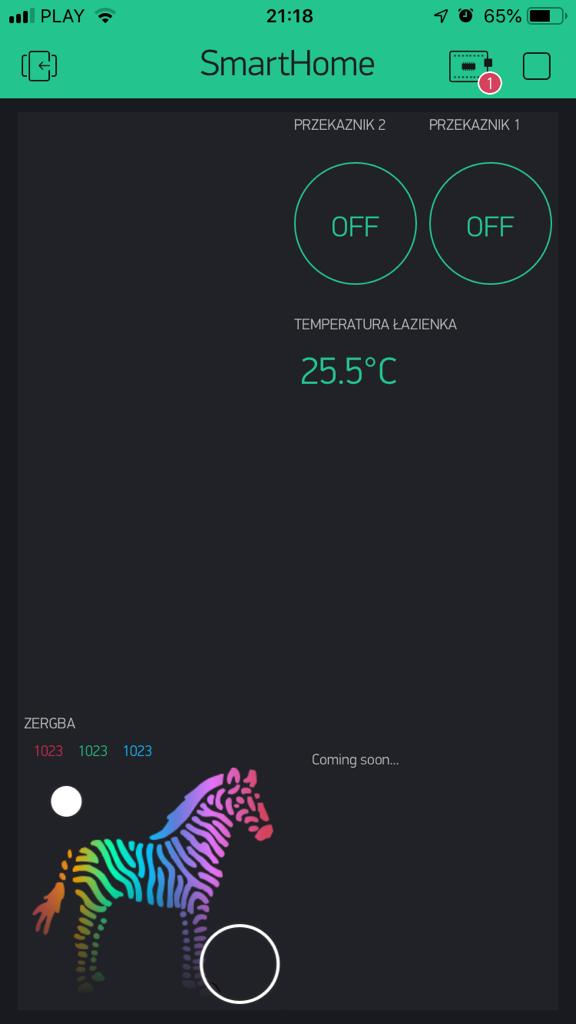
Yes, my project worked in past in SUPLA, only current sensor not, because people do not want use this.
So project from the hardware side work correctly. I want BLYNK because i feel better organization.
Great … now I need to evaluate SUPLA. Could someone with experience with both Blynk and SUPLA create a new topic comparing the two?
You’re halfway home! Would you happen to have any videos or screenshots of your project working with SUPLA? That would help us understand what you’re after. We’d be able to refer you to examples to achieve something similar with Blynk.
No I do not have any photos, I upload finish compilant file without code.
I found on Blynk community code for DS18B20 and ACS712, maybe we can connect together.
Hi @Erko, You’ve come to this forum wanting assistance in getting some Blynk-based code together to run on your custom hardware. Your topic title talked about “how to connect a few codes”, which I took to mean that you had some existing code samples that you’d successfully tested with your devices and that you needed to integrate together and add some Blynk functionality.
Forum members aren’t going to write your code for you, but they will probably give you a few pointers, highlight the precautions you need to take when coding with Blynk, and probably chip-in a few ideas and snippets of code that you could incorporate.
I started by suggesting that the first steps should be to share some functional data about one of your devices, along with existing code and some indication about what you wanted the finished Blynk app to do as far as this device is concerned. Because the devices seemed suitable for interaction in a smart home environment I also asked for information about your overall plan for how they might be used together.
So far you’ve provided a somewhat ambiguous list of GPIO ports and connections, but no indication about what these devices (switches, relays, LEDs etc) are intended to do, and what sort of functionality you’re looking For. for example…
You have two physical switches. Are they monetary or latching?
I assume that if you press one switch you want it to toggle one of the relays, but this is just a guess.
Is the LED supposed to light when one or both of the relays are activated? If so, why is there only one of them?
What sort of functionality are you looking for from Blynk? Do you just want to mirror the physical switches and LED with switch/LED widgets? Are you wanting some sort of timed control of the relays etc. etc. etc.
You’ve not shared any code, or Blynk app prototypes.
In answer to my question about integration and direct device to device communication you’ve said Yes, but not explained further, then thrown in some additional curved ball information about LORA, but not elaborated on it.
My analysis of the conversation so far is that there are a number of forum members who would be willing to contribute in some way, but that you aren’t really interested in doing the Blynk coding yourself - your primary focus seems to be on circuit design and construction.
If I’m reading this wrong then apologies - but you need to step-up and provide more usable information, and show some interest in getting your hands dirty with C++ and Blynk if you want any further assistance from the regulars here.
Yes, to his credit, @Erko has taken the time to download the Blynk app, create an account, create a project, get an auth token, install the Blynk library and execute a sketch capable of controlling two relays. That’s a good start. I just assumed he hadn’t even attempted integrating the other peripherals. He can certainly share whatever firmware he was working.
This is my topic, old topic. With inCan was noise problem but this is good product too.
Now Zamel has similar products for SUPLA.
I do not want selling my pcbs, If we will get/make code we can have good product to blynk.
I would start with blynk,
Yes, I have all things for blynk (I used blynk eventor) but I do not skills for writing a code.
Without code I do not use sensors etc.
I would like find help and I can give fine device instead.
Well, you have the attention of the entire Blynk Community. Let’s see if someone will volunteer to write your firmware.
Can you at least develop the Blynk Project (i.e., UI)? It’s just drag-n-drop. Pick which widgets you want to use. Arrange them on the canvas, possibly spanning multiple tabs. If you want the Project to monitor and control multiple devices, you may want to consider the Device Selector or Device Tiles widgets. I’d advocate Device Tiles. The user experience will be similar to,
You don’t need to write any code to develop the Blynk Project. You don’t even need to assign pins (physical or virtual) to the widgets. Just develop the user experience, then you can clone your project and share it with whomever volunteers to write your firmware.