some non-blynk related stuff again…
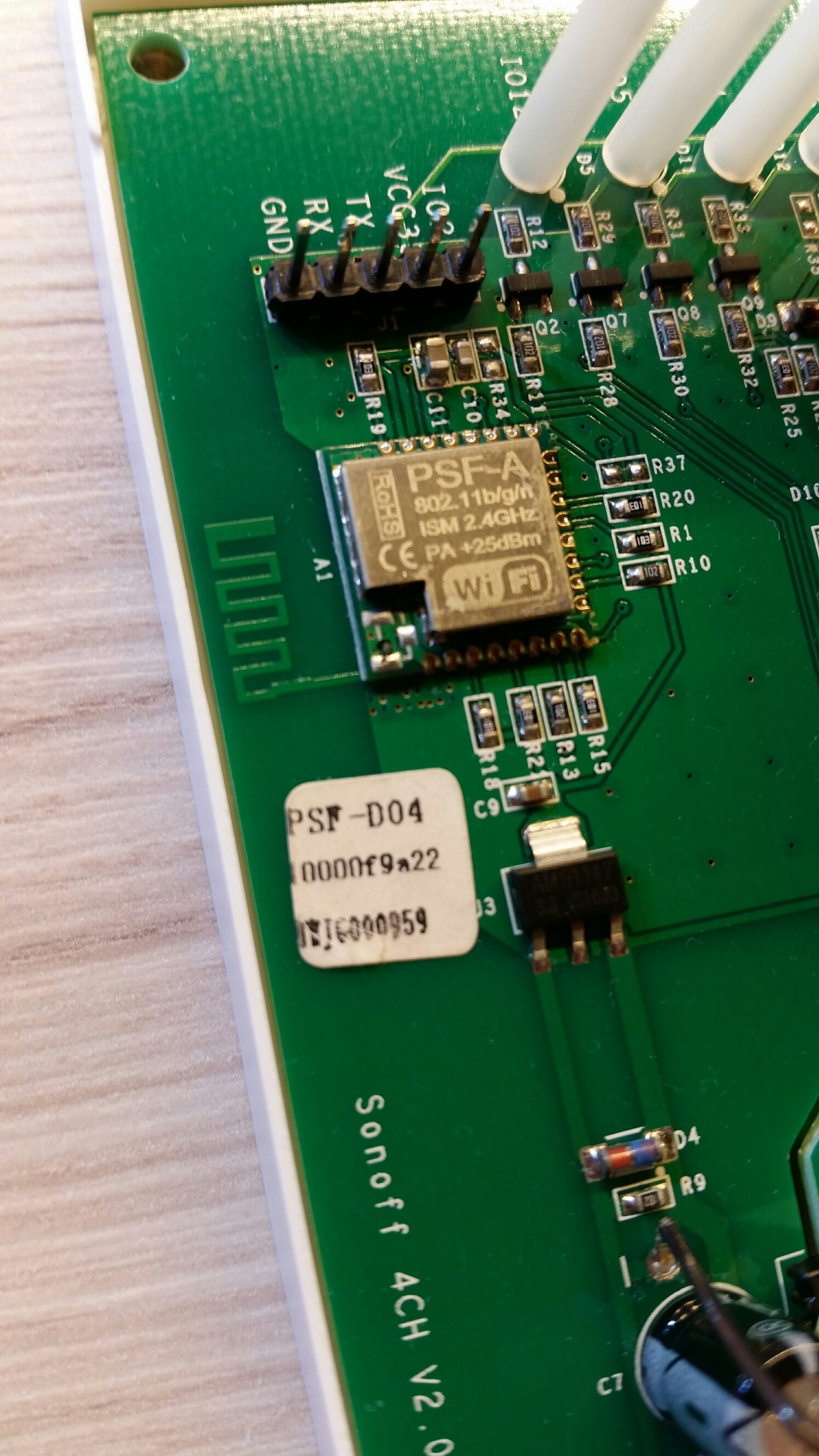
on a sonoff 4ch, pcb v2.0 board i have replaced the stock firmware, using the arduino ide.
i would like to set up interrupts for each button gpio. with the above setup, button 1 and button 4 works perfectly, however, button 2 and button 3 does not work. it seems that the interrupt is never executed, although i’ve checked with my multimeter that gpio9 and gpio10 are high, and is going low when i press the respective button.
what could be the reason for this? unfortunately i can not find a good pinout diagram for this esp8285, all the sites i’ve read says that all pins have interrupt function, except gpio16.
or something is not fully implemented in the arduino core, regarding digitalPinToInterrupt() function?
but than why works the same function for gpio0 and gpio14? i’m a bit confused regarding this.
Can you post the whole sketch? By all means it should work, though there are some really weird things going on with delay and ISR’s from what I can read here: https://www.arduino.cc/en/Reference/AttachInterrupt
It could be something to do with too much stuff going on. What happens if you scratch Button 1 and 4 and just use 2 and 3? E.g. comment those ISR’s out in setup()?
-edit
I’ve used ISR on the model railroad for moving and stopping a hot air balloon on a curtain rod (which works wonderfull) with some end-stop switches. But that’s only two ISR’s because I use I Nano there.
@wanek some pins are special and some are very, very special. 9 & 10 fall into the latter category.
I don’t have any ESP’s with pins 9 & 10 broken out but don’t you have to disable the very, very special feature of the pins to revert to a regular pin?
Think they are part of the flashing process but I could be wrong.
i see your point, but i did tried that already. even if i use only button 2 or button 3, it does never enters the isr. i’ve tried all combinations. only button 1 and button 4 works.
i did some further research, and maybe it has something to do with this:
it seems these are some “magic” pins, hooked up maybe to the flash?
i observed that on the wemos mini lite board they not even broke out…
@Costas, yes, see my above post.
theoretically they are / or not used by the flash memory chip. but igr says they should be usable on some models. i’m quite lost…
on the sonoff ch4, the are officially hooked up to button 2 and button 3, so they should be usable. maybe the interrupt does not work on them, only as normal i/o pins?
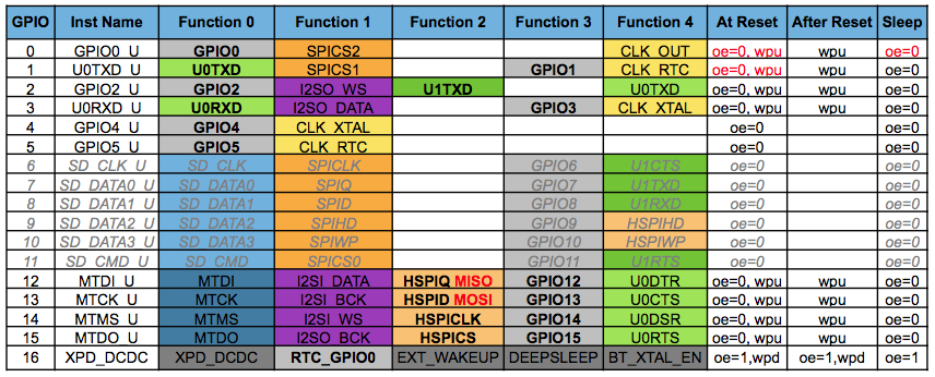
   GPIO      function                        schematic
   ---------------------------------------------------
   GPIO  0   Button 1                        E-FW
   GPIO  9   Button 2                        IO  9
   GPIO 10   Button 3                        IO 10
   GPIO 14   Button 4                        IO 14

   GPIO 12   Relay 1                         IO 12
   GPIO  5   Relay 2                         IO  5
   GPIO  4   Relay 3                         IO  4
   GPIO 15   Relay 4                         IO 15

   GPIO  2   Pin 1 Prog Header               SDA
   GPIO 13   Blue LED, Active Low            PWM 1

   GPIO  7   Not connected, jack (see TH16)  GPIO 07
   GPIO  8   Not connected, jack (see TH16)  GPIO 08

   3v3 - jack sleeve
   gnd - jack ring2
@Costas, do not forget, i’m talking about the esp8285, not8266 (i know on 8266 they are not usable, but 8285 is a bit different because of the built in flash)
on my board, there is a different version mcu, not like on the above photo. mine is covered with metal shield, so i can not see the “schematic” under it…
i also opened an issue on github, maybe some esp wizard will know the secret behind this…
I wouldn’t do that unless you have lots of them to do destructive testing on.
Does yours not have an external antenna socket?
Itead have ceramic aerial modules as PSF-B85 and external aerial modules as PSF-A85.
I would post on Itead’s site. They are fairly responsive.
so, again, gpio 9 and 10 are hooked up to pushbutton 2 and 3. also they are pulled up by 10k resistors. double checked the schematic and also measured with my dmm.


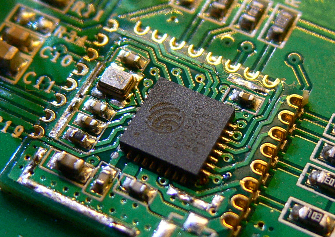
 not brute force actually i desoldered it, so no harm done!