Continuing the discussion from The smallest Wifi smartphone controlled 4WD car using ESP8266, Blynk and Arduino Code:
Hi sir,
I am interested in the above mentioned project and I am not engineering person but love to build up projects like this.
Here I am dissapointed that when I try to compile the sketch it shows error esp8266wifi.h library not found. I tried each and every thing that was mentioned on Google but with no results.
Is there any broken link.
I am using arduino ide 1.8.9 and successfully downloaded blynk library and esp8266 by esp community board.
Can you please help me out regarding this.
My email address guptamamtesh71@gmail.com
It will be very helpful of you if you can help me.
Have you installed the ESP8266 core ? If not use this link
http://arduino.esp8266.com/Arduino/versions/2.0.0/doc/installing.html
Paste this link in the arduino IDE preferences 
http://arduino.esp8266.com/stable/package_esp8266com_index.json
Thanks for your cooperation, I will try it today.
Hi madhukesh I have tried everything but failed to do it on arduino can I do the same by using nodemcu flasher.
It would be much better if when a forum user asks you a specific question, you answer that question rather saying “I have tried everything”.
Pete.
1 Like
Continuing the discussion from The smallest Wifi smartphone controlled 4WD car using ESP8266, Blynk and Arduino Code:
Hi sir, I have every possible way to compile the sketch and everytime an error occurs.
As I am only a hobbyist and no knowledge of coding and I have previously made a Wi-Fi car with help of tutorials mentioned in you tube videos and other sites.
I have been trying from last four days.
Can you please help me.
The error message I have mentioned earlier.
Thanks for your comment.
Have you installed the ESP core ? If yes then compile the code given below. Even then if you get errors then you have not installed the CORE. I have got the code compiled here.
/*
  Wifi/Blynk controlled 4WD car using ESP 8266
  Used Pin ESP07
  D5-14 motorA1 ; D6-12 motorA2
  D1-05 motorB1 ; D2-04 motorB2
  D4-02 Rightflasher
  RX-03 Leftflasher
  D7-13 Headlight ; tx-01 buzzer
*/
#include  <ESP8266WiFi.h>
#include  <BlynkSimpleEsp8266.h>

int X = 512;
int Y = 512;
int maximo = 0;
int Rflasher = 0;
int Lflasher = 0;
int buzzer = 0;
int police = 0;
int flasherLedState = LOW;          //Initial led state

long previousMillis = 0;        // Time control
long flasherLedInterval = 300;     // Interval time to run

#define RED 0
#define BLUE 0

byte whichLED = RED;
byte Red_State = LOW;
byte Red1_State = LOW;
unsigned long switchDelay = 250;
unsigned long strobeDelay = 50;
unsigned long strobeWait = strobeDelay;
unsigned long waitUntilSwitch = switchDelay;  // Initial state

char auth[] = "xxxxxxxxxxxx"; // You should get Auth Token in the Blynk App.

void setup()
{
  Serial.begin(9600);// Set console baud rate
  Blynk.begin(auth, "SSID", "PASS");// You will connect your phone to this Access Point and this is the password

  pinMode(14, OUTPUT); // Pin motor A1
  pinMode(12, OUTPUT); // Pin motor A2
  pinMode(2, OUTPUT); // Pin Rightflasher
  pinMode(3, OUTPUT); // Pin Leftflasher
  pinMode(5, OUTPUT); // Pin motor B1
  pinMode(4, OUTPUT); // Pin motor B2
  pinMode(1, OUTPUT); // PinoBuzzer

}

BLYNK_WRITE(V1)  // 0~1023
{
  int X1 = param[0].asInt();
  X = X1;
  int Y1 = param[1].asInt();
  Y = Y1;
}
BLYNK_WRITE(V2)//      slider PWM from 0 to 1023
{
  maximo = param.asInt();
}

BLYNK_WRITE(V3)     //      button Rightflasher
{
  Rflasher = param.asInt();
}

BLYNK_WRITE(V4)    //      button Leftflasher
{
  Lflasher = param.asInt();
}

BLYNK_WRITE(V5)    //      button buzzer
{
  buzzer = param.asInt();
}


BLYNK_WRITE(V7)     //      button police
{
  police = param.asInt();
}

void loop()
{
  Blynk.run();

  if (X != 512 && Y != 512)
  {

    if ( X > 311 && X < 711  &&  Y > 311 && Y < 711 ) //  Motor Stop
    {
      analogWrite(14, 0); //IN-1A motorA = 0
      analogWrite(12, 0);  //IN-1B


      analogWrite(5, 0); //IN-2A motorB = 0
      analogWrite(4, 0); //IN-2B
    }

    if ( X > 311 && X < 711  &&  Y > 711)  // motor forward
    {
      analogWrite(14, maximo); //motorA = maximo;
      analogWrite(12, 0);

      analogWrite(5, maximo);//motorB = maximo;
      analogWrite(4, 0);
    }

    if ( X > 311 && X < 711  &&  Y < 311)  // Motor backward
    {
      analogWrite(12, maximo);// motorA = maximo;
      analogWrite(14, 0);
      analogWrite(5, maximo);// motorB = maximo;
      analogWrite(4, 0);
    }
    if ( X > 711 &&  Y > 711)  // Right Forward
    {
      analogWrite(14, maximo);//motorA = maximo;
      analogWrite(12, 0);
      analogWrite(5, 0);//motorB = 0;
      analogWrite(4, 0);
    }

    if ( X < 311 &&  Y > 711)  // Left Forward
    {
      analogWrite(14, 0);//motorA = 0;
      analogWrite(12, 0);
      analogWrite(5, maximo);//motorB = maximo;
      analogWrite(4, 0);
    }

    if ( X > 711 &&  Y < 311)  // Right backwards
    {
      analogWrite(12, maximo);//motorA = maximo;
      analogWrite(14, 0);
      analogWrite(5, 0 );//motorB = 0;
      analogWrite(4, 0);
    }

    if ( X < 311 &&  Y < 311)  // Left backwards
    {
      analogWrite(12, 0);//motorA = 0;
      analogWrite(14, 0);
      analogWrite(5, maximo);//motorB = maximo;
      analogWrite(4, 0);
    }
  }

  if (Rflasher != 1 && Lflasher != 1)
  {
    if (police == 1)
    {
      digitalWrite(2, Red_State);
      digitalWrite(3, Red1_State);

      if ((long)(millis() - waitUntilSwitch) >= 0) {
        // time is up!
        Red_State = LOW;
        Red1_State = LOW;
        whichLED = !whichLED;  // toggle LED to strobe
        waitUntilSwitch += switchDelay;
      }

      //  police effect
      if ((long)(millis() - strobeWait) >= 0) {
        if (whichLED == RED)
          Red_State = !Red_State;
        if (whichLED == BLUE)
          Red1_State = !Red1_State;
        strobeWait += strobeDelay;
      }
    } else {
      digitalWrite(2, LOW);
      digitalWrite(3, LOW);
    }
  }

  unsigned long currentMillis = millis();    //Current time
  if (currentMillis - previousMillis > flasherLedInterval) //Logic of time verification
  {
    previousMillis = currentMillis;    // Saves the current time

    if (flasherLedState == LOW)
    {
      flasherLedState = HIGH;
    } else {
      flasherLedState = LOW;
    }
    if (Rflasher == 1 && police == 0)
    {
      digitalWrite(2, flasherLedState);
    } else {
      digitalWrite(2, LOW);
    }
    if (Lflasher == 1 && police == 0)
    {
      digitalWrite(3, flasherLedState);
    } else {
      digitalWrite(3, LOW);
    }
  }
  if (buzzer == 1)
  {
    tone(1, 500, 200); //Horn tone "FA"
  }
}
And also install the latest Blynk library. GitHub - blynkkk/blynk-library: Blynk library for IoT boards. Works with Arduino, ESP32, ESP8266, Raspberry Pi, Particle, ARM Mbed, etc.
There are many tutorials out there on how to install library.
To do this you need to have the .bin file of the project. Only then the flasher you are mentioning can flash the nodemcu. There is no option to type the code or push the .ino file on to the flasher(as per my knowledge).
Now you can try the above given code and compile it. It should compile.
Arduino 1.8.7
ESP core 2.4.2
Blynk lib 0.6.0
You can install the latest versions if you need.
1 Like
Thanks a lot for your kind cooperation and precious time to spend with me. God bless you.
The code is compiling now.
Thanks again.
1 Like
Hi I uploaded the sketch successfully but I am not able to connect esp with blynk app.
Have you entered all your credentials correctly ?
SSID
PASS
Server (if running on a local server)
AUTH
Show the sketch you are uploading.
Make sure you are entering all the credentials i mentioned above without any mistakes.
/*
  Wifi/Blynk controlled 4WD car using ESP 8266
  Used Pin ESP07
  D5-14 motorA1 ; D6-12 motorA2
  D1-05 motorB1 ; D2-04 motorB2
  D4-02 Rightflasher
  RX-03 Leftflasher
  D7-13 Headlight ; tx-01 buzzer
*/
#include  <ESP8266WiFi.h>
#include  <BlynkSimpleEsp8266.h>

int X = 512;
int Y = 512;
int maximo = 0;
int Rflasher = 0;
int Lflasher = 0;
int buzzer = 0;
int police = 0;
int flasherLedState = LOW;          //Initial led state

long previousMillis = 0;        // Time control
long flasherLedInterval = 300;     // Interval time to run

#define RED 0
#define BLUE 0

byte whichLED = RED;
byte Red_State = LOW;
byte Red1_State = LOW;
unsigned long switchDelay = 250;
unsigned long strobeDelay = 50;
unsigned long strobeWait = strobeDelay;
unsigned long waitUntilSwitch = switchDelay;  // Initial state

char auth [ ] =
";AUTH"  // You should get Auth Token in the Blynk App.

void setup()
{
  Serial.begin(9600);// Set console baud rate
  Blynk.begin(auth, "Wificar", "1234567890");// You will connect your phone to this Access Point and this is the password

  pinMode(14, OUTPUT); // Pin motor A1
  pinMode(12, OUTPUT); // Pin motor A2
  pinMode(2, OUTPUT); // Pin Rightflasher
  pinMode(3, OUTPUT); // Pin Leftflasher
  pinMode(5, OUTPUT); // Pin motor B1
  pinMode(4, OUTPUT); // Pin motor B2
  pinMode(1, OUTPUT); // PinoBuzzer

}

BLYNK_WRITE(V1)  // 0~1023
{
  int X1 = param[0].asInt();
  X = X1;
  int Y1 = param[1].asInt();
  Y = Y1;
}
BLYNK_WRITE(V2)//      slider PWM from 0 to 1023
{
  maximo = param.asInt();
}

BLYNK_WRITE(V3)     //      button Rightflasher
{
  Rflasher = param.asInt();
}

BLYNK_WRITE(V4)    //      button Leftflasher
{
  Lflasher = param.asInt();
}

BLYNK_WRITE(V5)    //      button buzzer
{
  buzzer = param.asInt();
}


BLYNK_WRITE(V7)     //      button police
{
  police = param.asInt();
}

void loop()
{
  Blynk.run();

  if (X != 512 && Y != 512)
  {

    if ( X > 311 && X < 711  &&  Y > 311 && Y < 711 ) //  Motor Stop
    {
      analogWrite(14, 0); //IN-1A motorA = 0
      analogWrite(12, 0);  //IN-1B


      analogWrite(5, 0); //IN-2A motorB = 0
      analogWrite(4, 0); //IN-2B
    }

    if ( X > 311 && X < 711  &&  Y > 711)  // motor forward
    {
      analogWrite(14, maximo); //motorA = maximo;
      analogWrite(12, 0);

      analogWrite(5, maximo);//motorB = maximo;
      analogWrite(4, 0);
    }

    if ( X > 311 && X < 711  &&  Y < 311)  // Motor backward
    {
      analogWrite(12, maximo);// motorA = maximo;
      analogWrite(14, 0);
      analogWrite(5, maximo);// motorB = maximo;
      analogWrite(4, 0);
    }
    if ( X > 711 &&  Y > 711)  // Right Forward
    {
      analogWrite(14, maximo);//motorA = maximo;
      analogWrite(12, 0);
      analogWrite(5, 0);//motorB = 0;
      analogWrite(4, 0);
    }

    if ( X < 311 &&  Y > 711)  // Left Forward
    {
      analogWrite(14, 0);//motorA = 0;
      analogWrite(12, 0);
      analogWrite(5, maximo);//motorB = maximo;
      analogWrite(4, 0);
    }

    if ( X > 711 &&  Y < 311)  // Right backwards
    {
      analogWrite(12, maximo);//motorA = maximo;
      analogWrite(14, 0);
      analogWrite(5, 0 );//motorB = 0;
      analogWrite(4, 0);
    }

    if ( X < 311 &&  Y < 311)  // Left backwards
    {
      analogWrite(12, 0);//motorA = 0;
      analogWrite(14, 0);
      analogWrite(5, maximo);//motorB = maximo;
      analogWrite(4, 0);
    }
  }

  if (Rflasher != 1 && Lflasher != 1)
  {
    if (police == 1)
    {
      digitalWrite(2, Red_State);
      digitalWrite(3, Red1_State);

      if ((long)(millis() - waitUntilSwitch) >= 0) {
        // time is up!
        Red_State = LOW;
        Red1_State = LOW;
        whichLED = !whichLED;  // toggle LED to strobe
        waitUntilSwitch += switchDelay;
      }

      //  police effect
      if ((long)(millis() - strobeWait) >= 0) {
        if (whichLED == RED)
          Red_State = !Red_State;
        if (whichLED == BLUE)
          Red1_State = !Red1_State;
        strobeWait += strobeDelay;
      }
    } else {
      digitalWrite(2, LOW);
      digitalWrite(3, LOW);
    }
  }

  unsigned long currentMillis = millis();    //Current time
  if (currentMillis - previousMillis > flasherLedInterval) //Logic of time verification
  {
    previousMillis = currentMillis;    // Saves the current time

    if (flasherLedState == LOW)
    {
      flasherLedState = HIGH;
    } else {
      flasherLedState = LOW;
    }
    if (Rflasher == 1 && police == 0)
    {
      digitalWrite(2, flasherLedState);
    } else {
      digitalWrite(2, LOW);
    }
    if (Lflasher == 1 && police == 0)
    {
      digitalWrite(3, flasherLedState);
    } else {
      digitalWrite(3, LOW);
    }
  }
  if (buzzer == 1)
  {
    tone(1, 500, 200); //Horn tone "FA"
  }
}
I am connecting by my mobile hot-spot
Wifi/Blynk controlled 4WD car using ESP 8266
Used Pin ESP07
D5-14 motorA1 ; D6-12 motorA2
D1-05 motorB1 ; D2-04 motorB2
D4-02 Rightflasher
RX-03 Leftflasher
D7-13 Headlight ; tx-01 buzzer
*/
Can you please check the pin configuration
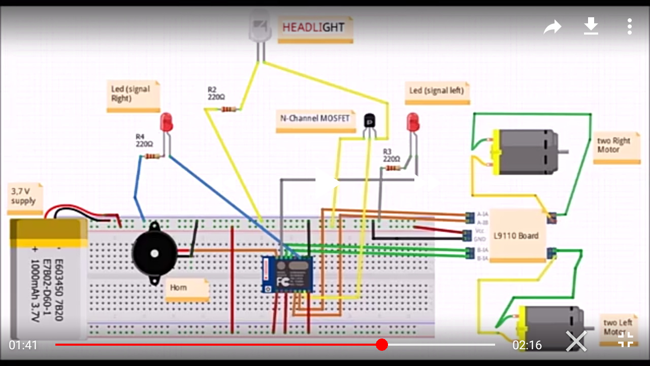
And let me know which virtual pin is for buzzer, headlight, motors, flasher, speed mentioned in the sketch I am also sending a screen shot of video.
Screenshot_2020-04-02-19-38-14|690x388
Have a look at the semicolon in the beginning of the auth token. Make sure its out side the double quotes.
Use Virtual pins V1,2,3,4,5,7
As virtual pins on the app settings.
This is my typing error occurred while pasting on the site rest is OK. I have double check everything.
Hi sir one thing more there is option of headlight but it seems no pin is assigned for it .
Which pin is configured for headlight.
Wifi/Blynk controlled 4WD car using ESP 8266
Used Pin ESP07
D5-14 motorA1 ; D6-12 motorA2
D1-05 motorB1 ; D2-04 motorB2
D4-02 Rightflasher
RX-03 Leftflasher
D7-13 Headlight ; tx-01 buzzer
What type of connection must I use if I am connecting blynk app by my mobile hot-spot.
Thanks again to guide me through out my project.
I have damaged one nodemcu and three esp8266 module to make this project successful but I am not going to give up until I fix it.
WiFi, assuming that your cellular data provider doesn’t block the Blynk data packets over the hotspot. Also, I’m not sure if you will be able to successfully run the hotspot and the Blynk app on the same device.
Pete.
1 Like
Thanks Sir.