ESP8266 Standalone send/receive data, write Pins HIGH/LOW

Hello everbody,
I already used the following code with USB connection to my arduino board. Now I am triieng the same code with an ESP8266 Standalone. The problem is it doesnt work out, I am not able to send or receive data from/to the blink app.
The Value from the sliders are not shown in the Value Displays as they used to be.

Thank you for your help.


#define BLYNK_PRINT Serial
#include <ESP8266WiFi.h>
#include <BlynkSimpleEsp8266.h>

SimpleTimer timer;


// You should get Auth Token in the Blynk App.
// Go to the Project Settings (nut icon).
char auth[] = "0d71XXXXXXXXXXXXXXXX0176";

// Your WiFi credentials.
// Set password to "" for open networks.
char ssid[] = "FRXXXXXXXXXXXXXXXX90";
char pass[] = "643xXXXXXXXXXXXXXXXX671";


int Button1;
int Slider1;
int Slider2; 
int Slider4; 


int Display = Slider1 + Slider2  + Slider4;

void setup()
{ 
  
  Serial.begin(9600);
  Blynk.begin(auth, ssid, pass);
  
  Blynk.syncVirtual(V1);
  Blynk.syncVirtual(V2); 
  Blynk.syncVirtual(V9); 
  Blynk.syncVirtual(V6);

  pinMode(0,OUTPUT);  
  pinMode(1,OUTPUT);
  pinMode(6,OUTPUT); 


}

void loop()
{ 
  Blynk.run();
  timer.run();
  
}


BLYNK_WRITE(V1) //Slider1
{
  Slider1 = param.asInt();
  Display = Slider1 + Slider2 + Slider4;
  //if(Slider2 != 0){                   // just a hack for initial boot when 2nd slider doesn't yet have a value
    Blynk.virtualWrite(V3, Display);
    Blynk.virtualWrite(V5, Slider1);
  //}  
}

BLYNK_WRITE(V2) { //Slider2
  Slider2 = param.asInt();
  Display = Slider1 + Slider2 + Slider4;
  Blynk.virtualWrite(V4, Slider2);
  Blynk.virtualWrite(V3, Display);
}


BLYNK_WRITE(V9) { //Slider4
  Slider4 = param.asInt();
  Display = Slider1 + Slider2 + Slider4;
  Blynk.virtualWrite(V10, Slider4);
  Blynk.virtualWrite(V3, Display);
}


             BLYNK_WRITE(V6) {
              Button1 = param.asInt();
              if (Button1 ==1 && Display <= 225 ){
              
              digitalWrite(0, HIGH);  
                timer.setTimeout(Slider1/8.7*1000, ACTIONOFF1);

              digitalWrite(1, HIGH);
                timer.setTimeout(Slider2/5.4*1000, ACTIONOFF2);
              
              digitalWrite(6, HIGH);
                timer.setTimeout(Slider4/8.7*1000, ACTIONOFF4);
              
            }}


void ACTIONOFF1()
{
  digitalWrite(0, LOW);
  Blynk.virtualWrite(V6,0);
}

void ACTIONOFF2()
{
  digitalWrite(1, LOW);
  Blynk.virtualWrite(V6,0);
}

void ACTIONOFF4()
{
  digitalWrite(6, LOW);
  Blynk.virtualWrite(V6,0);
}

Did you change the board in the Blynk app from Arduino to ESP?
Sketch looks OK, add Serial.print() calls to see where it fails.

1 Like

Thank you for the Tip.
I wrote the code new based on the example. That is how i solved my first problem . It works but I dont know what the problem was :smiley:

 #define BLYNK_PRINT Serial
#include <ESP8266WiFi.h>
#include <BlynkSimpleEsp8266.h>

SimpleTimer timer;

char auth[] = "0d716XXXXXXXXXXXXXXb08a0176";

// Your WiFi credentials.
// Set password to "" for open networks.
char ssid[] = "FRITXXXXXXXXXXXX90";
char pass[] = "643XXXXXXXXXXX8671";


int Slider1;
int Display;
int Button1;

void setup()
{
  // Debug console
  Serial.begin(9600);

  Blynk.begin(auth, ssid, pass);
  Blynk.syncVirtual(V1); 
  pinMode(0,OUTPUT);
   
}

void loop()
{
  Blynk.run();
   timer.run();
}
BLYNK_WRITE(V1) //Slider1
{
  Slider1 = param.asInt();

  Serial.println("parameter1");
  Display = Slider1;
    Blynk.virtualWrite(V3, Display);
    Blynk.virtualWrite(V5, Slider1);
  
}

BLYNK_WRITE(V6) {
              Button1 = param.asInt();
              if (Button1 ==1 && Display <= 225 ){
              Serial.println("HUGH");
               digitalWrite(0, HIGH);  
                timer.setTimeout(Slider1/8.7*1000, ACTIONOFF1); 
      }}

void ACTIONOFF1()
{
  digitalWrite(0, LOW);  
  Blynk.virtualWrite(V6,0);
  Serial.println("LOW");
}

That leads me to the next problem…
I try to put the 0 pin HIGH and than LOW but for some reason it doesnt work out.
I hope you can help me with that one too.

THX Thomas

Are you getting neither HIGH nor LOW?

What range is your slider?

1 Like

I dont get HIGH and LOW.
The sliders range is 0 to 200 . That means the conditions for the if action are fullfilled.

When I upload a sketch without blynk, only the commands to put a pin HIGH it works out, but I the blynk context it doesnt work.

I solved the problem on my own.
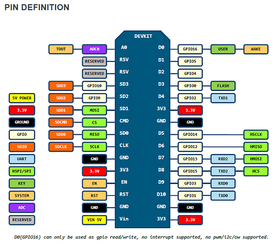
If you want to write pin D1 high u have to write pin gpi05 high witch means for the code:

 digitalWrite(5, HIGH); // to write pin D1 high on the board
``

PINS VERTEILUNG

If you are compiling the sketch as a NodeMCU or WeMos you can use “D1” within the digitalWrite because your board selection in the IDE has pin translation tables.

That said I only ever use GPIO references and not the silkscreen references used by NodeMCU / WeMos etc. It means you can port your code to all ESP8266’s if you stick to the GPIO references.