Hello, first post here, but I’m getting kind of frustrated over trying to connect my UNO to WiFi with the ESP8266 chip.
I’ve manged to change it’s baud rate to correspond to the Arduinos.
It responds to the AT commands I send it, and I’m able to connect it to a network.
I’ve also made a regulator that supplies a 3.3V output (delivering enough current as well).
I’ve followed this tutorial to try to get it to work, but…
It keeps saying “ESP not responding”
So, I have some questions that I’ve been scratching my head for days trying to figure this out for my project:
Do I need a converter (FTDI?) for my ESP?
Should the TX on the ESP go to the UNOs RX pin? And vice versa?
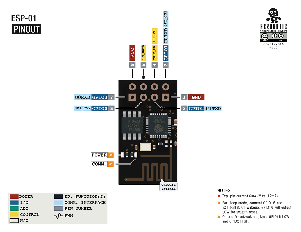
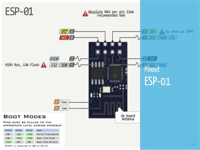
*I don’t have the CH_PD, GPIO 0 and GPIO 2 on my ESP. Instead I have an EN pin and two others (will check on Monday). Of these pins (and the others , i.e. the RST pin), which should be set to 3.3V/GND/float?
Do the GND of the ESP/regulator have to be connected tot he Arduino in some form? I’ve tried connecting the grounds together.
Are you aware that the ESP8266 has more processing power and probably more memory than your Arduino and that it can be programmed with the same Arduino IDE software, using (almost) identical code?
Because of this, the chances are that the Arduino Uno is redundant.
If you’re using the ESP-01 like the one in your diagram (although that’s not clear from your comment about not having the same pin assignments) then you’ve chosen a difficult package to work with. You’d actually be better with something like the Wemos D1 Mini as it has an onboard USB and more GPIO pins available.
If you want to continue with your original setup then I think your issue is with the fact that the Uno only has one serial port. You seem to be using this to connect the Uno to your PC and have it talk to the ESP. You should probably be using Software Serial to talk to the ESP. The correct GPIO pins for this communication are defined in the softwareserial.h library file, but aren’t the TX/RX pins on the Uno.
Depends on the type of ESP9266 board you have… there are a few
Yes… well sorta… you should be using Software Serial with an UNO, so make a few changes in the sketch and use digital pins 2 (RX) and 3 (TX) instead.
// Hardware Serial on Mega, Leonardo, Micro...
//#define EspSerial Serial1  // Comment OUT this part

// or Software Serial on Uno, Nano...
#include <SoftwareSerial.h>  // Use these thse parts
SoftwareSerial EspSerial(2, 3); // RX, TX
Again, depending on the type of board you have.
If you have a full Dev board with built in USB, then don’t bother with the Arduino… follow this tutorial instead
If you have something entirely different, let us know what it is.
Shared GND is necessary whenever you have multiple PSUs (like Arduino on USB and ESP8266 via your regulator.
But if you built your own 3.3v regulator circuit, then the cap is for smoothing (optional, but recommended) but the resistors are not required… as they are used to drop from a 5v to 3.3v supply as per the shown diagram that shared the single 5v PSU for both Arduino and ESP8266.
So it is not required to use the pins that are labelled TX and RX on the UNO? Because this doesn’t show on the diagram that I referred to earlier.
Ahh, thanks for clearing up on the common ground question. I’m using a PCB that was used previously in a PSU (school project), that has a regulator that can be adjusted to the correct voltage and also capacitors for smoothing out the signal. It’s been tested to deliver 3.3V and enough current. This doesn’t have to be connect to the Arduino in any way, does it?
I need the Arduino because of the I/O pins that will be used in a school project. I now see that my model has the IO0 and IO2 pins (I just noticed, sorry). The only difference is that the GP was removed from the labelling. The back of the ESP8266-01
For “simplicity” you MUST use Software Serial with the UNO and designate digital pins as availed. Details already shown above, and G gle is your friend
Sorry for sounding a little dumb, but this diagram confuses me. If I use the digital pins as the equivalent of the TX/RX pins (this is because it’s SoftwareSerial, right?), then where should they be connected to the ESP8266? If possible, could you also please tell me which other pins are to be set to High/GND/float?
I know, it’s just that there are so many contradicting diagrams and tutorials out there that make me confused. But thank you for helping me out and clarifying things!
Not sure on the definitive number as of yet (we’re beginning the project this week). But we are to use the Arduino to control multiple elements within a miniature house. So digital pins for servos, light circuitry and analog for e.g. temperature sensors or potentiometers. Blynk (or internet connectivity at all) isn’t actually required, but I’ve already showed my teachers what I’m able to do with Blynk (door control, temperature, etc.) and so I really want it to be an integrated part of my project, while also being able to use a power regulating circuit for the ESP to show competence.
To the RX and TX pins on the ESP (softRX to TX & softTX to RX… think speaking from your mouth to someone else’s ear, and their mouth to your ear)
The UNO can’t use it’s original RX/TX pins because they are already in use with the USB programming port… thus the need for SoftSerial. But the ESP can use it’s RX/TX ports and then transfer that signal to it’s WiFi… thus it becomes a simple adapter.
Thank you for clearing that up! Still somewhat unsure about the RST and EN though, as diagrams showed different answers.
Also, in the ESP8266_SHIELD example sketch, it asks me for the ESPs baud rate
// Your ESP8266 baud rate: #define ESP8266_BAUD 115200
I’ve already programmed the ESP to use 9600 as baud rate. Does this line of code notify the program of the ESPs baud rate, or does it convert it to 9600? I ask because I’ve read that the baud rate of the ESP and the Arduino has to match up.
The ESP is acting as a modem for your Arduino.
The Arduino needs to be told what communication speed the ESP is expecting, so the line of code you referred to tells the Arduino how fast to send and listen for data from the ESP.
If you’ve set the ESP to 9600 then you need to change that line to 9600 as well.
Actually, 9600 is a little slow - you’ll probably find that you get snappier response by setting the ESP back to its default then updating that line of code to match.
You do have to match them up… and SoftSerial requires 9600 (well, is more stable), particularly on a slower Arduino. Since you have already set the ESP then just change the UNO with this.


