Yes. You’ll need to install the ESP core into the Arduino IDE…
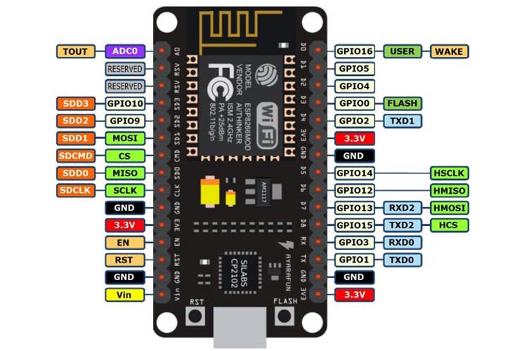
You’ll also need to ensure that you understand the relationship between GPIOs and the numbers printed on the board…
And know which pins are ‘safe’…
You’ll also need to include the correct libraries…
Give us a shout if you get stuck.
Pete.