Is your project staying connected to Blynk as confirmed in the app?
Are you trying to power the relay and ESP01 from the Arduino?
If you haven’t already done so I would start by controlling the onboard LED of the Arduino with Blynk. You then know you have the basics right and can move on to the relay.
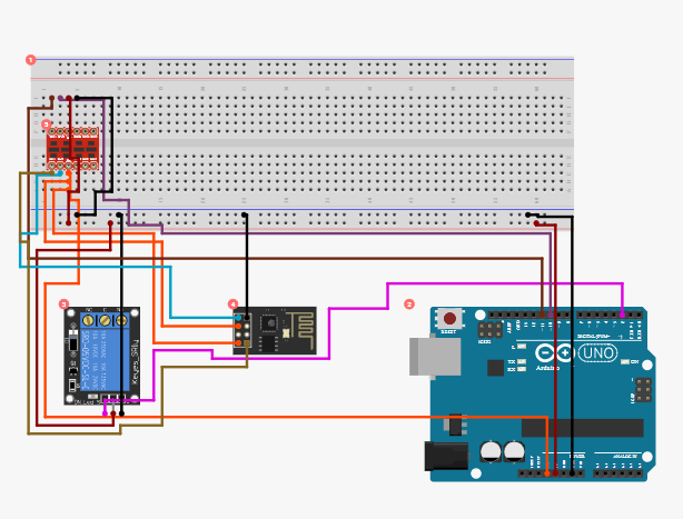
Meantime produce a high resolution image of exactly how you have wired everything up.
We can assist further when we know you can control an LED.
The ESP8266 module that you’re using actually has much more processing power than the Arduino that you’re connecting it to, and it can be programmed using the Arduino IDE editor in exactly the same way.
The problem is that the type of ESP8266 that you’re using (assuming that it looks like the one in the wiring diagram) doesn’t have many of the connections to the chip made available as pins on the circuit board connector, so is quite difficult to use as a replacement for the Arduino.
I’d suggest that you look at the Wemos D1 Mini, along with the Wemos Relay shield and a twin base to plug them into.
The Wemos is a 3.3v device (it can be powered by either 5v or 3.3v, but the GPIO logic pins expect a 3.3v signal and 5v will destroy the device without some additional circuitry). However, the device that’s on your breadboard (I can’t see what it is from the diagram) seems to be being powered from the 3.3v pin on the Arduino, so should be fine.
I started-off by using an Arduino, then added an Ethernet shield and then used an ESP8266 instead of the Ethernet shields to give me Wi-Fi capability. I eventually realised that for 99% of the projects I do, the Arduino is redundant and the ESP is a much better MCU.
I received a couple from a random online seller a few days ago rated at 10A. Less than $1.20 a piece incl delivery. I use a couple of those mini breadboards that clip together, 1 for a genuine WeMos and 1 for the relay as I’m not a fan of stacking (or soldering)
I really like these dual bases: https://www.ebay.co.uk/i/192001462381
They have mounting holes that make them easy to fix them into a case and it’s easy to pop the Wemos or relay out if you need to swap them. The base links GPIO 5 from the Wemos across to the relay, so no extra wiring is needed.
Some people are also selling triple bases now as well. I ordered a couple recently but haven’t got around to using them for anything yet.
Not only redundant but the Arduino is more expensive and bulky. Even the Adruino clones like the Micro and Mini are pretty nice and inexpensive alternative. But I quickly latched onto the STM32, ESP8266, and now the ESP32. At least now a lot of small, inexpensive, and yet very powerful alternatives.
I started with Nano and I still love it, but soon after I started to experiment with various ESP8266 boards, especially after NodeMCU experience, I found Arduino completely obsolete. Even if you’re dealing with multiple analog devices, you can always use multiplexer and voltage divider with NodeMCU and get the same end result.
Of course I have used other modules as well. ESP-01 is suitable for non-complicated applications only and it’s pinout is real PITA, I found it impractical for project usage.
ESP-07 is perfect for low wifi signal environments because it has external antenna port but it’s development board is rather impractical if you want to use it for breadboard experiments as it won’t fit one. It will fit Wemos D1 dual expansion base with some rearrangements, and it’s a straight fit for Witty cloud base, though, but it’s definitely not breadboard type of device, just like ESP-01. It also can be power hungry, I saw it drawing over 500mA from time to time.
Wemos D1 is fine if you like to use expansion boards and build simple projects fast, NodeMCU is the best one by far from my experience.
NodeMCU is most suitable for 24/7 operation, it’s barely warm even when in very hot environment, it’s not particularly power hungry, and it has embedded CP2102 - just plug in your USB cable and you’re ready to go. Besides this facts, it’s always the first one to reconnect to the router after restart, and it’s keeping the connection like a beast. Even a nest of 6-7 devices working side by side didn’t create enough noise to cause any problems.
I was eager to get my hands on his younger brother, ESP32. I was thrilled with embedded Basic interpreter and BLE, but from hardware point of view, ESP32 generates to much heat and power consumption is very high (way over 0,5A for stable operation), and for that reason I would never use it instead of NodeMCU in my projects. But there is no doubt that ESP32 is extremely powerful MCU, and this chipset has bright future for sure.
And to be frank, Sonoff TH10 was to blame for my initial interest in ESP8266 and home automation concept. It’s a simple, cheap and powerful device, but I didn’t like EWELink software, nor the possibility to depend on a cloud. It’s also very easy to integrate it to your Blynk project, GPIO12 triggers the relay, and you still have GPIO14 at disposal, even GPIO13 if you can live without on-board LED can be assigned to do something else. I used GPIO14 to connect DHT-22 sensor, for example. As far as you’re not trying to use DIO instead of DOUT flash method, you will be fine with your Sonoff. Using DIO on this board will get you nothing but trouble, one in ten attempts of flashing will be successful. If you search various communities on this matter, all you will find will be advices for a stronger power supply, but flashing problems has nothing to do with it. In fact, TH-10 will awake and join the network still being on your USB port after successful flash. So, I can’t stress this enough, if you’re playing with Sonoff devices, always use DOUT. The same applies for most of ESP-01 devices as well, so if you wan’t to save your self from wtd reset misery, forget about DIO.
Here is one group ESP greeting to Blynkers from my desk
Well, this is a community, right? So what’s the point of community if we are not sharing our knowledge/experience with others? That’s just my way of thinking - share and learn from shared by others. So please don’t hesitate to ask - if I know the answer, I will not keep it for myself
Unfortunately, many tutorials available on web are misleading or incomplete, I’ve learned that hard way, knowing almost nothing on the matter when I was starting this journey. Flashing procedure for Sonoff devices is by far most notorious case, hundreds of topics addressing the same problem, and guys who successfully made their projects on the same platform answering it’s all about power supply - it’s simply impossible that they didn’t have any troubles trying to flash it with DIO, but still - not a word on it. Nobody ever mentioned that it has to be DOUT. That just took me some additional time before I decided to try just about everything and forget about tutorials, and solution was very simple, the same one that solved my wdt reset trouble when I was playing with ESP-01…