Do you mean the RJ45 to the A and B of the MAX485? I was forwarding the instruction of this PDF, nevertheless, I did try to invert the wire - no success.
I suppose this LED on your MAX485 is always on as mine, am I right?
So I was thinking about how to connect to the Serial1, and not to wait for the FDTI adapter from China (because it will take more than a month to come to my country), and in the end, I figured out I can use the original CC-USB-4S485-150U EPever cable for debugging 
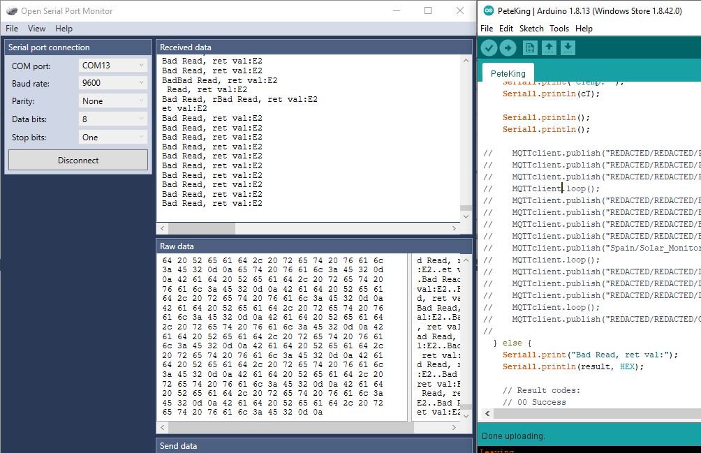
I connected to the D4 and GND as you instructed (to the CC-USB) and I can read the Serial1.
Now, I did try to install this MQTT client to my PC (mosquitto) and to get the Wemos connected to it, but as the MQTT and this mosquitto it’s a bit confusing to me I ended commenting the whole part regarding the MQTT in your code.
If I understand well you were using the MQTT just to communicate (forward) the result to “into the world” - am I right? Anyhow, I don’t need this for this my test purpose.
As my solar charge controller is on a remote site, I can’t test it today. If the weather condition will be OK I will test it Friday evening and let you know the result.
One more question - do you connect as follow:
DI of the MAX485 to the TX of the Wemos and
RO of the MAX485 to the RX of the Wemos?
Thank you very much for now.
Paolo