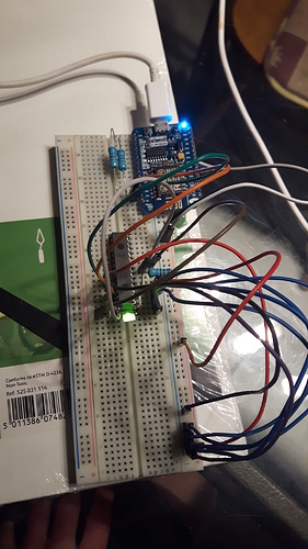
ESP8266, MCP23017, Blynk virtual port

Hi! i i2c’d up and mcp23017 to a esp8266 nodemcu devkit v0.9.

.
The point i am right now is the communication ok.
I can get the code below working.
My question is how can i fireout the mcp23017 gpio with Blynk virtual port.
Ive allready got Blynk working for other project before so no problem to get the app working.
I know that i have to define the virtual port to the gpio on the mcp23017 but i can’t figure it out.
My coding skills result in copy/paste :slight_smile:
I would really appreciate help!

#include Adafruit_MCP23017.h
#include Wire.h
#include ESP8266WiFi.h
#include BlynkSimpleEsp8266.h
#define BLYNK_PRINT Serial

Adafruit_MCP23017 mcp;

char auth[] = "";
char ssid[] = "";
char pass[] = "";


void setup()
{
  mcp.begin();
  mcp.pinMode(0, OUTPUT);
  mcp.pinMode(1, OUTPUT);
  
  Serial.begin(9600);
  Blynk.begin(auth, ssid, pass);
}

void loop()
{
  delay(100);
  mcp.digitalWrite(0, HIGH);
  mcp.digitalWrite(1, LOW);
  delay(100);
  mcp.digitalWrite(0, LOW);
  mcp.digitalWrite(1, HIGH);
  
  Blynk.run();
}

This is not a Blynk question, this is a general Arduino code question. Google around for both devices and see what examples you can find, then once you know how they work, you can apply Blynk commands to the ESP and have it do the work with the port expander.

Like here…

And here…

http://www.esp8266.com/viewtopic.php?f=19&t=660

Hi Gunner!
The esp is communcating with the mcp, i get the 2 led flashing and interswitching on/off with100 ms delay.
I want to have an example of how trigger mcp gpio with a command line with BLYNK app virtual port.
Would be sort of like:

mcp.pinMode(0, OUTPUT); = Blynk.virtualWrite(1, “gpa0”);

So when i set a button to virtual port 1 into the BLYNK app, it will give a booleen state of 1 to the mcp pin (gpa0). :slight_smile:

At the point for using all 16 gpio on the mcp for switching on and off purpose with BLYNK app running on android:)

Ok have a nice day!

#define BLYNK_PRINT Serial // Comment this out to disable prints and save space
#include <SPI.h>
#include <ESP8266WiFi.h>
#include <BlynkSimpleEsp8266.h>
#include <SimpleTimer.h>
/**********************************************************************************/
#include <Wire.h>
#include “Adafruit_MCP23017.h” //https://github.com/adafruit/Adafruit-MCP23017-Arduino-Library
Adafruit_MCP23017 mcp;
SimpleTimer timer;

char auth[] = “YOUR_BLYNK_AUTH_CODE”;
char ssid[] = “yyyyyyyyyyy”;
char pass[] = “zzzzzzzzzz”;
/********************************************************************************************************/
BLYNK_WRITE(V0) // V0 is the number of Virtual Pin For Read From BLYNK APP
{
int pinValue = param.asInt();

mcp.digitalWrite(0, pinValue);
Serial.print("pinValue0 = ");
Serial.println(pinValue);
}
BLYNK_WRITE(V1) // V1 is the number of Virtual Pin For Read From BLYNK APP
{
int pinValue1 = param.asInt();

mcp.digitalWrite(1, pinValue1);
Serial.print("pinValue1 = ");
Serial.println(pinValue1);
}
BLYNK_WRITE(V2) // V2 is the number of Virtual Pin For Read From BLYNK APP
{
int pinValue2 = param.asInt();

mcp.digitalWrite(2, pinValue2);
Serial.print("pinValue2 = ");
Serial.println(pinValue2);
}
BLYNK_WRITE(V3) // V3 is the number of Virtual Pin For Read From BLYNK APP
{
int pinValue3 = param.asInt();

mcp.digitalWrite(3, pinValue3);
Serial.print("pinValue3 = ");
Serial.println(pinValue3);
}

void senddata()
{
int a = mcp.digitalRead(1);
int b = mcp.digitalRead(4);

Blynk.virtualWrite(V4, a); // Send Value to BLYNK APP V4
Blynk.virtualWrite(V5, b); // Send Value to BLYNK APP V5

}
/******************************************************************************************************************/
void setup()
{
Serial.begin(9600); // See the connection status in Serial Monitor
Blynk.begin(auth, ssid, pass);
mcp.begin();
mcp.pinMode(0, OUTPUT);
mcp.pinMode(1, OUTPUT);
mcp.pinMode(2, OUTPUT);
mcp.pinMode(3, OUTPUT);
// mcp.pinMode(1, INPUT); no need to set as input

timer.setInterval(1000L, senddata);
}

void loop()
{
Blynk.run(); // Initiates Blynk
timer.run(); // Initiates SimpleTimer
}

1 Like

Use This Code

Great code I got to try it and it seems to work properly to turn on and off the relay, of course I can continue up to V16 for each integrated MCP23017. But if I would like to use three mcp23017 for a total of V48 outputs, how should I set the code? Thank you so much for your attention :wink:

1 Like

hello, do you still have this working?
i can’t get my mcp23017 chip to work …
on the serial monitor it appears that the esp sends the data but the chip does not respond

How is your MCP connected to your ESP?
What I2C bus address is your MCP set to?

Pete.

it is connected to D1 and D2

This is exactly like this:


 #define BLYNK_PRINT Serial // Comment this out to disable prints and save space
  #include <SPI.h>
  #include <ESP8266WiFi.h>
  #include <BlynkSimpleEsp8266.h>
  #include <SimpleTimer.h>
  / *************************************************  ********************************* /
  #include <Wire.h>
  #include “Adafruit_MCP23017.h” //https://github.com/adafruit/Adafruit-MCP23017-Arduino-Library
  Adafruit_MCP23017 mcp;
  SimpleTimer timer;

  char auth [] = "YOUR_BLYNK_AUTH_CODE";
  char ssid [] = "yyyyyyyyyyy";
  char pass [] = "zzzzzzzzzz";
  / *************************************************  ****************************************************  ***** /
  BLYNK_WRITE (V0) // V0 is the number of Virtual Pin For Read From BLYNK APP
  {
  int pinValue = param.asInt ();

  mcp.digitalWrite (0, pinValue);
  Serial.print ("pinValue0 =");
  Serial.println (pinValue);
  }
  BLYNK_WRITE (V1) // V1 is the number of Virtual Pin For Read From BLYNK APP
  {
  int pinValue1 = param.asInt ();

  mcp.digitalWrite (1, pinValue1);
  Serial.print ("pinValue1 =");
  Serial.println (pinValue1);
  }
  BLYNK_WRITE (V2) // V2 is the number of Virtual Pin For Read From BLYNK APP
  {
  int pinValue2 = param.asInt ();

  mcp.digitalWrite (2, pinValue2);
  Serial.print ("pinValue2 =");
  Serial.println (pinValue2);
  }
  BLYNK_WRITE (V3) // V3 is the number of Virtual Pin For Read From BLYNK APP
  {
  int pinValue3 = param.asInt ();

  mcp.digitalWrite (3, pinValue3);
  Serial.print ("pinValue3 =");
  Serial.println (pinValue3);
  }

  void senddata ()
  {
  int a = mcp.digitalRead (1);
  int b = mcp.digitalRead (4);

  Blynk.virtualWrite (V4, a);  // Send Value to BLYNK APP V4
  Blynk.virtualWrite (V5, b);  // Send Value to BLYNK APP V5

  }
  / *************************************************  ****************************************************  *************** /
  void setup ()
  {
  Serial.begin (9600);  // See the connection status in Serial Monitor
  Blynk.begin (auth, ssid, pass);
  mcp.begin ();
  mcp.pinMode (0, OUTPUT);
  mcp.pinMode (1, OUTPUT);
  mcp.pinMode (2, OUTPUT);
  mcp.pinMode (3, OUTPUT);
  // mcp.pinMode (1, INPUT);  no need to set as input

  timer.setInterval (1000L, senddata);
  }

  void loop ()
  {
  Blynk.run ();  // Blynk Initiates
  timer.run ();  // Initiates SimpleTimer
  }

Hopefully there are more connections than that. It should be like this:

3v3 —> VCC
GND —> GND
D2 —> SDA
D1 —> SCL

I think you misunderstood my I2C address question.
The MCP boards I’ve used have have solder pads to allow you to set the I2C address of the device. If the board is set to (or defaults to) an I2C address that is different to what the Adafruit library expects when you use:

then the MCP will be invisible to the Adafruit library.
You could run an I2C scanner sketch on your ESP to ensure that the board is being detected and what address it is using.
Looking again at my topic on the MCP board will tell you more about how to tell the Adafruit library which address to use.

Pete.

I’m only using the microchip mcp23017, I saw your topic, but honestly I couldn’t understand how to apply it to my use :frowning:

In that case, I think it’s up to you to define the I2C address. I’d take a look at the specs for the chip and go from there, and run an I2C scanner on your ESP.

This is now clearly nit a Blynk related issue.

Pete.

the problem is that i don’t know anything about programming, i’m starting now, i thought it would be easier to insert this mcp in esp, but even without blynk i couldn’t make it work …
even with ready projects …
i wanted to relieve the use of doors at mcu8266, at the moment i use 10 doors each, but i think this one will have to stay anyway.

I’m sorry to say that this sentence makes no sense to me.

At this stage, I don’t think that our problem is to do with coding, more to do with the support circuitry that you have connected to your MCP. Pins A0, A1 and A2 of the MCP control the I2C address of the device and cannot be left floating. Once you’ve decided on the I2C address that you want to use and configured these three pins accordingly then you should run an I2C scanner sketch on your ESP to confirm that the ESP can see the MCP on the I2C bus at the desired address.
If the address you use isn’t the default used by the Adafruit library then you need to modify your code to tell the library which bus address to use. Details if this are included in my other post.

Personally, as someone who is very comfortable designing and building electronic circuits, I can see no reason at all to use a bare MCP chip and the necessary support components rather than buying a readymade board like the one from Waveshare.

Pete.

ok, i will see if i buy any ready plate
thanks for now

This topic was automatically opened after 3 days.