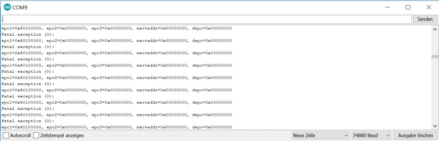
Everytime i connect my board to the USB-Port, the serial monitor is showing strange symbols and repeating it constantly (as you can see in the picture i uploaded). The Wifi Chip and the USB Port of the ESP are also getting really hot. Like i am burning my fingers hot.
I guess I destroyed it, but want to know why? I charge the ESP by connecting it with the USB-Port to my computer. I am also using a L9110s to drive two DC Motors which are supplied with a 12V trafo.
Could it be the power supply? Or is it maybe something in my code? Is it maybe overloaded?
The default baud rate for the NodeMCU is usually 74880
If you change your serial monitor to this then I think you’ll see the boot messages from the NodeMCU and that they will show that the device is stuck in a constant reboot loop.
This could be caused by a bad flash, so re-flashing our code may fix the issue, a corrupted or incompatible library, or the devices that you have connected to the NodeMCU may be causing the issue.
Setting your debug serial monitor speed to 74880 instead of what you have at the moment:
Serial.begin(115200);
will allow you to see both the messages from the NodeMCU and your debug serial output without changing the baud of the IDE serial monitor.
Try re-flashing the code, probably at a lower upload speed.
Try disconnecting all of the connections from your NodeMCU
Try using a different/better Micro USB cable or a different USB port on your PC incase it’s a power issue.
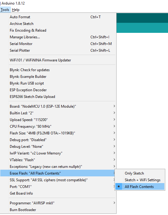
Try using the Erase Flash : All Flash Contents when uploading your sketch
Try uploading a simple sketch instead
If none of these work then you may need to use ESPtool to erase the flash contents entirely.
I will try all of your advices and let you know what helped in the end.
Do you think when I know how to fix the problem, I will also understand the reason for the problem? Because it is the second time that happened to my board and I really want to avoid it next time.
What do you mean with these two points exactly? (Not the one with uploading a simple sketch. I already tried this) I can’t really find something in the community or internet for those. Is there an explenation somewhere?
PS: I tried the points above and nothing of them worked.
I can’t find a fitting topic for the erase flash in the community. And all the instructions on other plattforms seems a bit dubios for me.
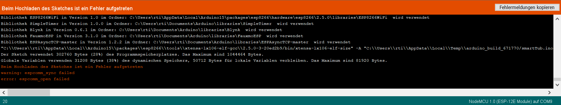
Do you know where i can find a good explanation for it? Do I need to upload a certain code for it? If yes, I need to mention that arduino software always shows espcomm error while trying to upload sketches.
As it’s already been pointed-out, it’s much better to copy and paste this stuff between triple backticks rather than post a screenshot.
Your coad upload is failing, so none of the things you’ve tried so far have had any effect, the same failed code is still running on the NodeMCu and has not been updated with anything different. so, your problem is actually “I can’t upload code to my NodeMCU”.
Try holding-down the RST button on your NodeMCU while you plug-in the USB cable, then release the button and try doing a code upload.
I’d also suggest upgrading to the latest ESP core (it seems you are running V2.5.0 when the lates is 2.6.3). This is done via Tools/Board/Boards manager and scrolling down to the bottom of the list and finding esp8266 by esp8266 community.
The latest core has a very different clde upload process and may give more insight into the issue.
esptool.py v2.8
Serial port COM9
Connecting........_____....._____....._____....._____....._____....._____.....____Traceback (most recent call last):
  File "C:\Users\rti\AppData\Local\Arduino15\packages\esp8266\hardware\esp8266\2.6.3/tools/upload.py", line 65, in <module>
    esptool.main(cmdline)
  File "C:/Users/rti/AppData/Local/Arduino15/packages/esp8266/hardware/esp8266/2.6.3/tools/esptool\esptool.py", line 2890, in main
    esp.connect(args.before)
  File "C:/Users/rti/AppData/Local/Arduino15/packages/esp8266/hardware/esp8266/2.6.3/tools/esptool\esptool.py", line 483, in connect
    raise FatalError('Failed to connect to %s: %s' % (self.CHIP_NAME, last_error))
esptool.FatalError: Failed to connect to ESP8266: Timed out waiting for packet header
esptool.FatalError: Failed to connect to ESP8266: Timed out waiting for packet header

_
I tried reset and flash button while “connecting…” but it’s still the same issue.
Yes I guess buying a new one is the best solution. I am just wondering what the reason for this is. Especially because it is the second one which has this problem.
I am thinking of buying a Wemos D1 R2 V2.1.0 Wifi board instead. Maybe this won’t happen to it then.
Anyway, thank you very much for your time and I hope it was not too exhausting. I am still a beginner and don’t get some points right away.
I don’t know what causes this.
I’ve never had this happen to me in a way that was unrecoverable, so I’m not really able to comment.
I certainly would not buy a Wemos D1 R2 board myself, as far as I’m concerned. I’m a fan of the D1 Mini and MIni Pro boards, but the D1 R2 is the worst of both worlds as far as I’m concerned.
I’ll mark this topic as solved, as it’s not Blynk related anyway.
Try pulling up D4(GPIO2) with 3k3 resistor and pulldown D8(GPIO15) with 3k3 resistor . Or use a different pin other then D4. I am not sure if this works. But give it a try. And leave a update for us if that solves the problem.
I wanted to try another ESP from an old project first, before I’d go for your advice. When I connected it to the laptop it showed the same error message like the two ESPs before.
My L9110s is connected to a 12V traffo which I put on and off with a plugbar. I found out that everytime I first turn on the plugbar with the Traffo and afterwards connect the ESP to the Laptop erverything works fine (with every ESP). When I do it the other way around, the ESP starts to go into the error loop.
I guess it has to do something with the motor pins A1A, A1B, B1A and B1B.