It’s been a while since I posted a project… so here is one I’ve been working on.
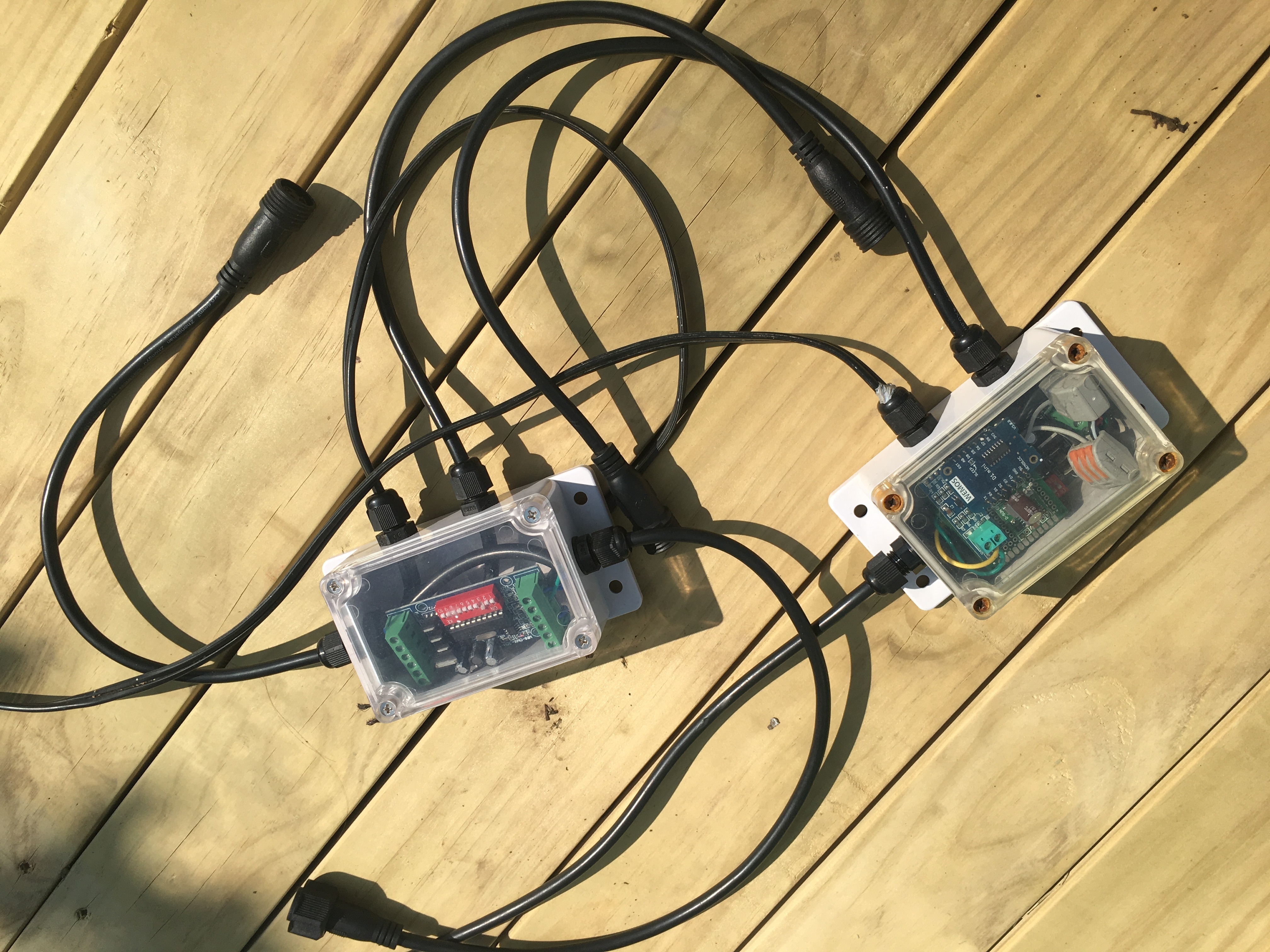
I created a DMX512 Controller for RGB LEDs which runs on a ESP8266.
Additional hardware is required: RGB 3-Chan Decoder and MAX485 Module. I use these 9W RGB lights in my garden powered by a AC240V to DC24V IP67 transformer.
Additional librarys are also required: FastLED and ESPDMX.
Wiring:
ESP8266 GPIO-02 to DI on the MAX485 Module.
Make sure the Module is powered by 5V and is grounded to the ESP8266.
MAX485 Module A output goes to the decoder D+ input
MAX485 Module B output goes to the decoder D- input
The decoders can be chained together by passing the D+/D- to the next decoder. Max 41 decoders.
The decoder outputs to the RGB light’s 4 inputs.
The code isnt perfect, but it works!  I hope that it helps someone on the internet because this code was incredibly hard to figure out myself. haha
//#define BLYNK_DEBUG
#define BLYNK_PRINT Serial
#include <ArduinoOTA.h>
#include <ESP8266WiFi.h>
#include <BlynkSimpleEsp8266.h>
#include <ESPDMX.h>
#include <FastLED.h>
#include <hsv2rgb.h>
#include <pixeltypes.h>
/*
Wifi Credentials
*/
#define WIFI_SSID "xxxxxxxxxxxxxxxxxx"
#define WIFI_PASS "xxxxxxxxxxxxxxxxxx"
#define AUTH "xxxxxxxxxxxxxxxxxx"
#define OTA_HOSTNAME "DMX-LEDS"
//#define LOCAL_SERVER IPAddress(192, 168, 1, 2)
#define vPIN_INFO V0
#define vPIN_CHAN_SELECT V1
#define vPIN_CHAN_DISP V2
#define vPIN_COLOUR_DISPLAY V3
#define vPIN_HUE V11
#define vPIN_SAT V12
#define vPIN_BRI V13
#define vPIN_GROUP V6
#define vPIN_RAINBOW V7
#define vPIN_RAINBOW_SPEED V8
#define vPIN_RAINBOW_OFFSET V9
BlynkTimer timer;
DMXESPSerial dmx;
int varHue = 56, varSat = 255, varBri = 255, varRainbowSpeed = 50, varRainbowOffset = 0, varChan, varTotalChannels = 20, varGroup;
int arrayMemory[20][4];
int timerInfo, TimerHue, TimerRainbow, TimerChan;
String CurrentHexRGB;
void setup() {
Serial.begin(115200);
WiFi.mode(WIFI_STA);
#ifdef LOCAL_SERVER
Blynk.begin(AUTH, WIFI_SSID, WIFI_PASS, LOCAL_SERVER, 8080);
#else
Blynk.begin(AUTH, WIFI_SSID, WIFI_PASS);
#endif
while (Blynk.connect() == false) {}
ArduinoOTA.setHostname(OTA_HOSTNAME);
ArduinoOTA.begin();
dmx.init();
timerInfo = timer.setInterval(1000, []() {
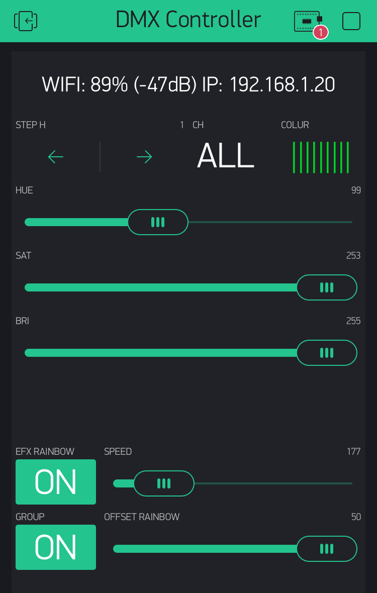
Blynk.virtualWrite(vPIN_INFO, String("WIFI: ") + String(map(WiFi.RSSI(), -105, -40, 0, 100)) + String("% (") + WiFi.RSSI() + String("dB)") + String(" IP: ") + WiFi.localIP().toString() );
});
varGroup = 1;
Blynk.virtualWrite(vPIN_CHAN_DISP, "ALL");
Blynk.virtualWrite(vPIN_GROUP, 1);
Blynk.syncVirtual(vPIN_RAINBOW_OFFSET, vPIN_RAINBOW_SPEED, vPIN_RAINBOW);
}
BLYNK_WRITE(vPIN_HUE) {
varHue = param.asInt();
ProcessHSV(varChan, varHue, varSat, varBri);
Blynk.setProperty(vPIN_COLOUR_DISPLAY, "color", CurrentHexRGB);
}
BLYNK_WRITE(vPIN_SAT) {
varSat = param.asInt();
ProcessHSV(varChan, varHue, varSat, varBri);
Blynk.setProperty(vPIN_COLOUR_DISPLAY, "color", CurrentHexRGB);
}
BLYNK_WRITE(vPIN_BRI) {
varBri = param.asInt();
ProcessHSV(varChan, varHue, varSat, varBri);
Blynk.setProperty(vPIN_COLOUR_DISPLAY, "color", CurrentHexRGB);
}
BLYNK_WRITE(vPIN_RAINBOW) {
if (param.asInt()) {
varGroup = 1;
Blynk.virtualWrite(vPIN_CHAN_DISP, "ALL");
Blynk.virtualWrite(vPIN_GROUP, 1);
if (timer.isEnabled(TimerRainbow)) timer.disable(TimerRainbow);
TimerChan = 1;
TimerHue = arrayMemory[TimerChan - 1][0];
TimerRainbow = timer.setInterval(varRainbowSpeed, []() {
TimerHue++;
if (TimerHue >= 255) TimerHue = 0;
ProcessHSV(TimerChan, TimerHue, varSat, varBri);
});
} else {
timer.disable(TimerRainbow);
}
}
BLYNK_WRITE(vPIN_RAINBOW_SPEED) {
varRainbowSpeed = param.asInt();
Blynk.syncVirtual(vPIN_RAINBOW);
}
BLYNK_WRITE(vPIN_RAINBOW_OFFSET) {
varRainbowOffset = param.asInt();
Blynk.syncVirtual(vPIN_RAINBOW);
}
BLYNK_WRITE(vPIN_CHAN_SELECT) {
if (!varGroup) {
varChan = param.asInt();
Blynk.virtualWrite(vPIN_CHAN_DISP, varChan);
Blynk.virtualWrite(vPIN_HUE, arrayMemory[varChan - 1][0]);
Blynk.virtualWrite(vPIN_SAT, arrayMemory[varChan - 1][1]);
Blynk.virtualWrite(vPIN_BRI, arrayMemory[varChan - 1][2]);
Blynk.setProperty(vPIN_COLOUR_DISPLAY, "color", CurrentHexRGB);
} else {
varChan = 1;
Blynk.virtualWrite(vPIN_CHAN_DISP, "ALL");
}
}
BLYNK_WRITE(vPIN_GROUP) {
varGroup = param.asInt();
Blynk.syncVirtual(vPIN_CHAN_SELECT);
}
void ProcessHSV(int channel, int hue, int sat, int bri) {
arrayMemory[channel - 1][0] = hue;
arrayMemory[channel - 1][1] = sat;
arrayMemory[channel - 1][2] = bri;
CHSV hsv(hue, sat, bri);
CRGB rgb;
hsv2rgb_spectrum(hsv, rgb);
CurrentHexRGB = String("#") + String( ( rgb.r << 16) | (rgb.g << 8 ) | rgb.b, HEX);
if (varGroup) {
for (int i = 1; i < varTotalChannels; i++) {
if(varRainbowOffset){
hue = hue + (varRainbowOffset * i);
CHSV hsv(hue, sat, bri);
CRGB rgb;
hsv2rgb_spectrum(hsv, rgb);
}
dmx.write((i * 3) - 2, rgb.r);
dmx.write((i * 3) - 1, rgb.g);
dmx.write((i * 3) - 0, rgb.b);
}
} else {
dmx.write((channel * 3) - 2, rgb.r);
dmx.write((channel * 3) - 1, rgb.g);
dmx.write((channel * 3) - 0, rgb.b);
}
}
void loop() {
Blynk.run();
ArduinoOTA.handle();
dmx.update();
timer.run();
}
—-
Some media