I’m searching a solve about this problem for a long time. I read all topics and tried many different variations but still cant fix it maybe i can learn my faults with your helps.
My capacitive soil sensor value is constant at 4095. If i scale it 0-100 it’s constant at 100. How can i see it correctly with all details?
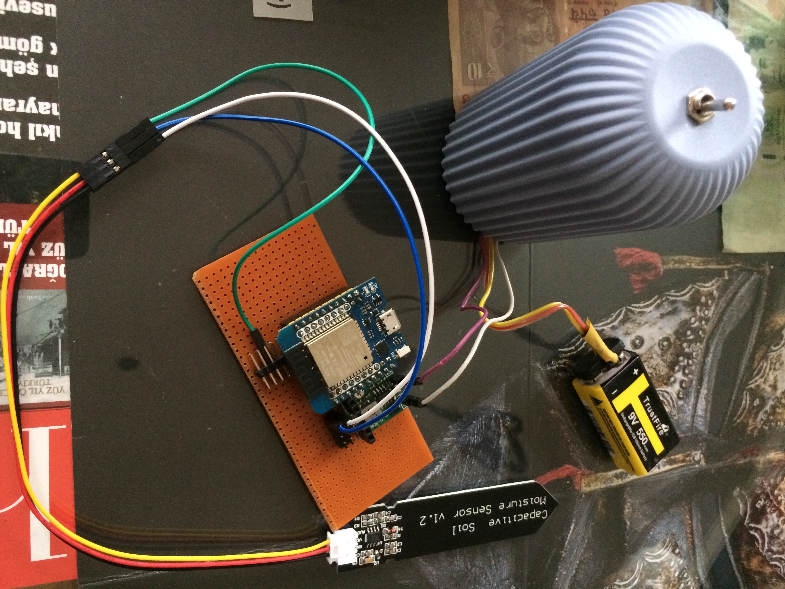
I’m working with a mh-et live esp32 mini kit with 9V battery and regulating to 5V for esp32 and all sensors(tried with 3,3V esp pin for soil vcc and result still constant value). By the way DHT11 is working well.
Also I tried GPI34 and 35 pins but still reading constant 4095. If I wont connect sensor the value is 0.
When sensor data pin connected to V0, value turns 4095.
My failed sketch with adc1;
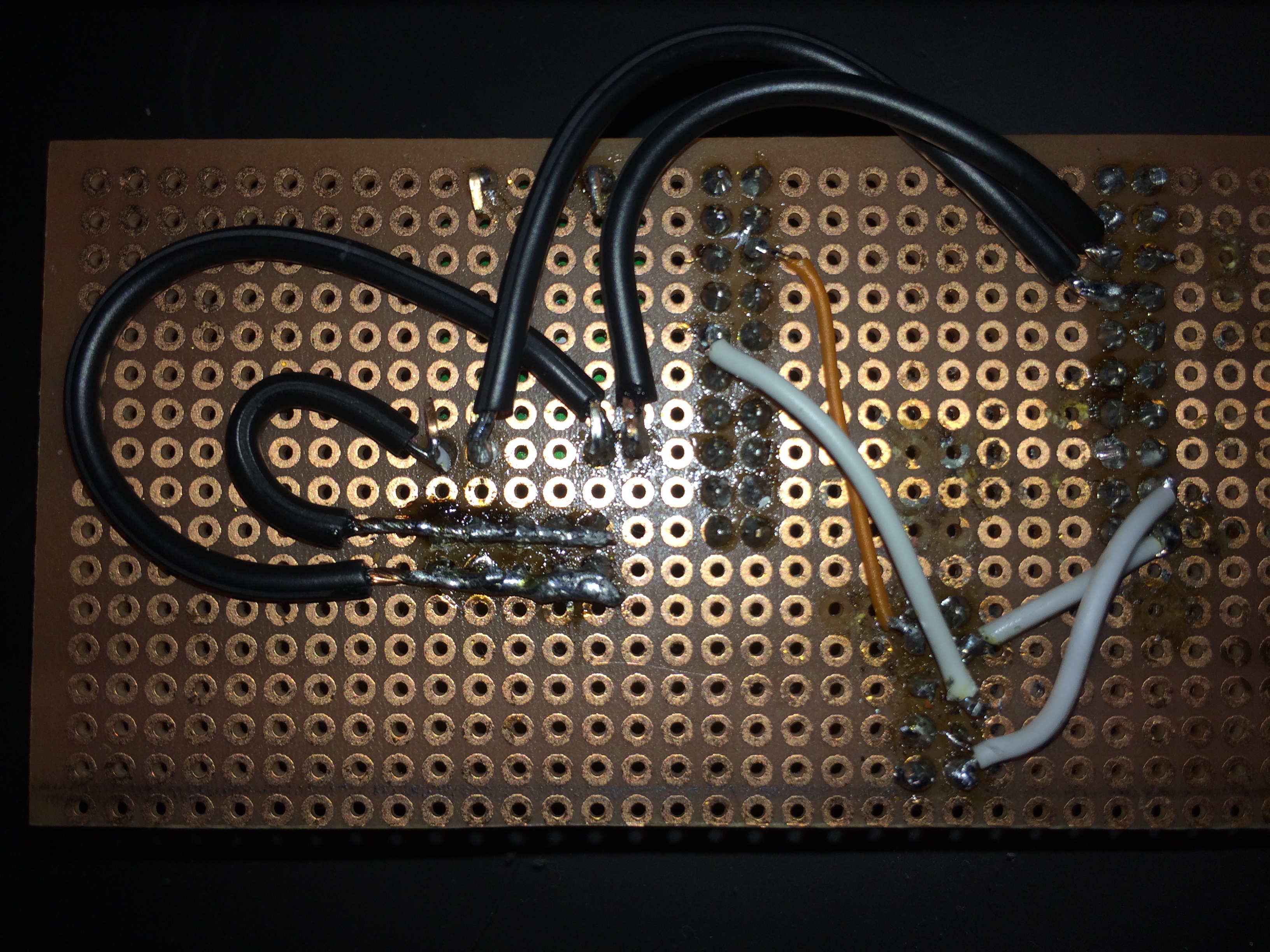
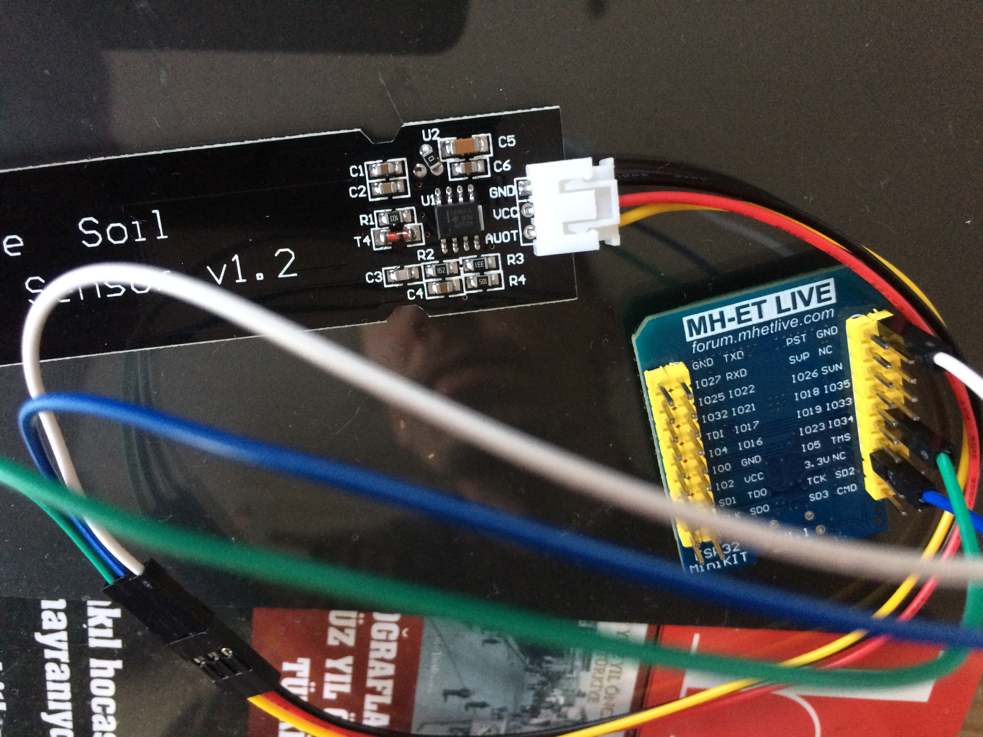
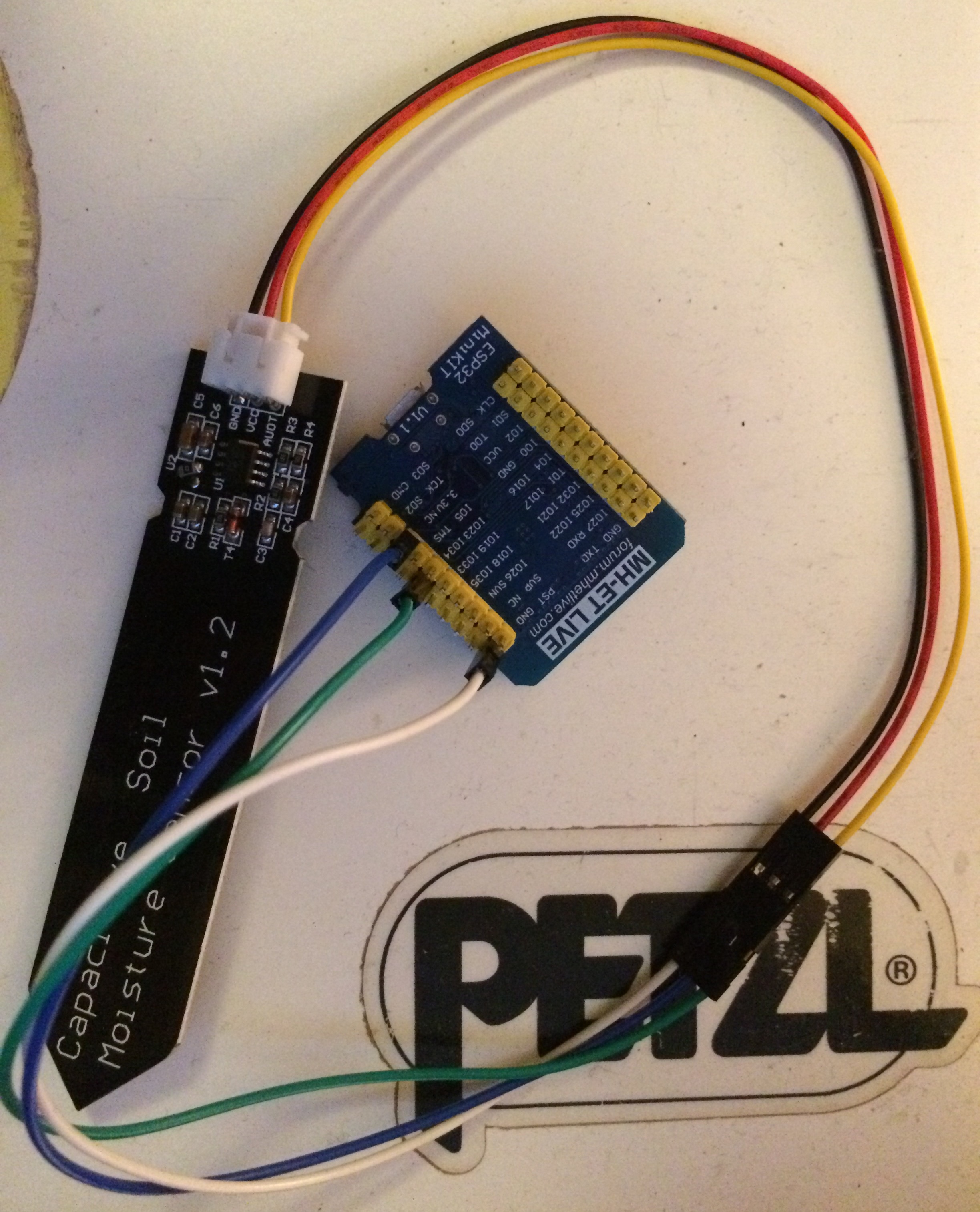
It’s the soil sensor that I need to see in close-up, with enough detail to see the details of what how each pin is labelled, which may require a photo of both sides of the board.
Don’t read the sensors that often, especially not the DHT. It’s slow as hell and will give you other problems later on!
If you try a bare minimum sketch, do you get correct readings from the sensor?
Google gave me some examples, change analogRead() to match your setup:
void setup() {
  Serial.begin(9600); // open serial port, set the baud rate as 9600 bps
}
void loop() {
  int val;
  val = analogRead(A0); //connect sensor to Analog 0
  Serial.println(val); //print the value to serial port
  delay(2000);
}
[/quote]
Hello distans,
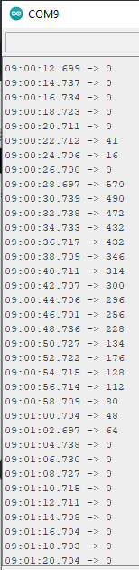
I observed that from serial monitor,
It shows data for a lil time(maybe not but looks like capacitor discharge chars)
Actually, I think the “sensor” (combined with a resistor) is acting like a simple voltage divider and are changing the reactance on the square wave generated by the 555 timer, which is the signal you’re trying to measure. I think!
Is the small 8-pin chip labeled NE555, TLC555 or another “555” combination?
I think you’re right!
Ehh… Isn’t pinMode() only used for digital I/O? @PeteKnight?
And I’m following many links about capacitive soil sensor fails, fix, calibration… really confused for now.
Maybe my soil sensors need some modifications.
Soil sensor input voltage 5V(MP1584EN output) and sensor value is constantly going to 0 to 4095. Its like ekg diagram when sensor stable in water or air. Maybe need to calibration now?
There are other more advanced functions to use with the ADC pins that can be useful in other projects.
analogReadResolution(resolution): set the sample bits and resolution. It can be a value between 9 (0 – 511) and 12 bits (0 – 4095). Default is 12-bit resolution.
analogSetWidth(width): set the sample bits and resolution. It can be a value between 9 (0 – 511) and 12 bits (0 – 4095). Default is 12-bit resolution.
analogSetCycles(cycles): set the number of cycles per sample. Default is 8. Range: 1 to 255.
analogSetSamples(samples): set the number of samples in the range. Default is 1 sample. It has an effect of increasing sensitivity.
analogSetClockDiv(attenuation): set the divider for the ADC clock. Default is 1. Range: 1 to 255.
analogSetAttenuation(attenuation): sets the input attenuation for all ADC pins. Default is ADC_11db. Accepted values:
ADC_0db: sets no attenuation. ADC can measure up to approximately 800 mV (1V input = ADC reading of 1088).
ADC_2_5db: The input voltage of ADC will be attenuated, extending the range of measurement to up to approx. 1100 mV. (1V input = ADC reading of 3722).
ADC_6db: The input voltage of ADC will be attenuated, extending the range of measurement to up to approx. 1350 mV. (1V input = ADC reading of 3033).
ADC_11db: The input voltage of ADC will be attenuated, extending the range of measurement to up to approx. 2600 mV. (1V input = ADC reading of 1575).
analogSetPinAttenuation(pin, attenuation): sets the input attenuation for the specified pin. The default is ADC_11db. Attenuation values are the same from previous function.
adcAttachPin(pin): Attach a pin to ADC (also clears any other analog mode that could be on). Returns TRUE or FALSE result.
adcStart(pin), adcBusy(pin) and resultadcEnd(pin): starts an ADC convertion on attached pin’s bus. Check if conversion on the pin’s ADC bus is currently running (returns TRUE or FALSE). Get the result of the conversion: returns 16-bit integer.
Maybe you should look at increasing the analogSetCycles() setting to smooth out the readings?
After all, i prefered to use [Arrays] for averaging adc values.
Now your ESP can read pretty well(as David says; “every ESP needs calibration if want to use ADC well” but divider worked for me".
Now I’m watching my capacitive soil sensors brilliant results, incredible!
 .
.