please i need help
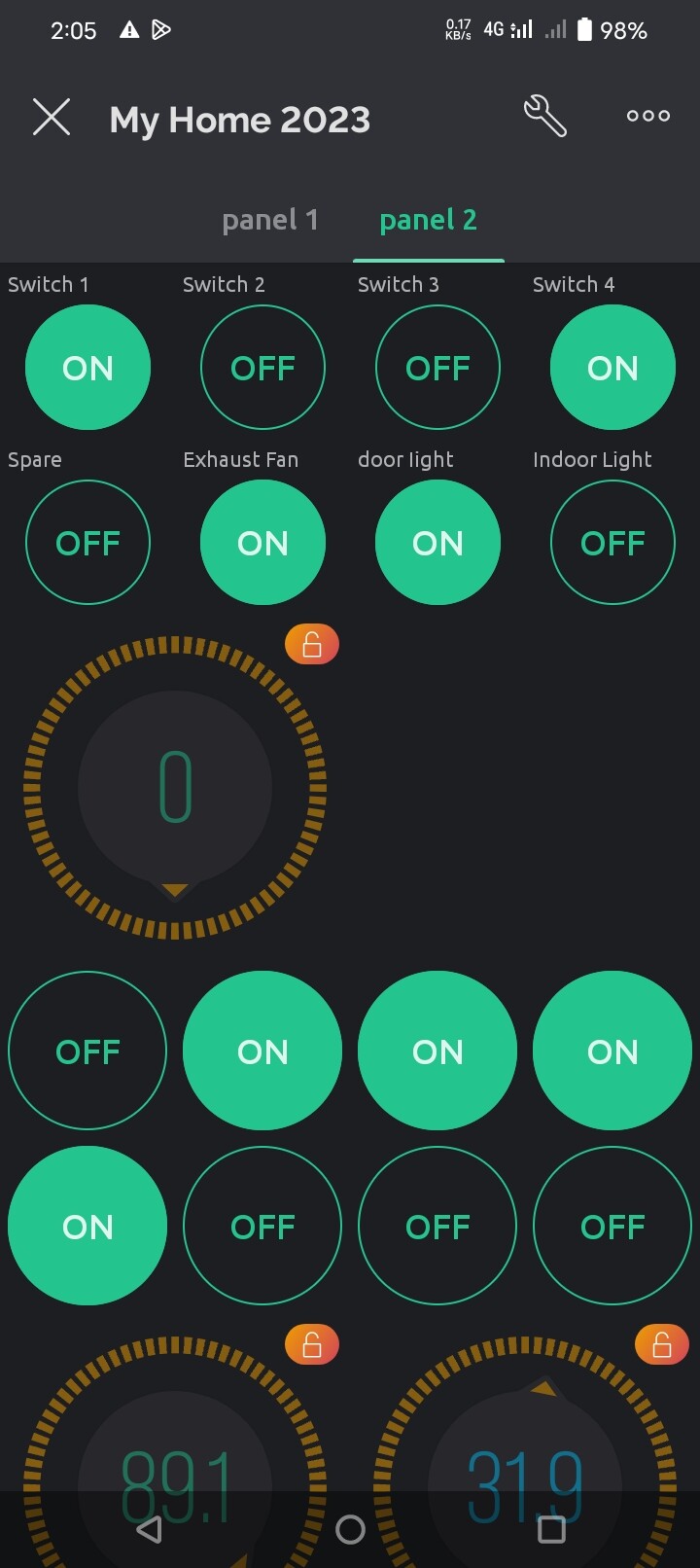
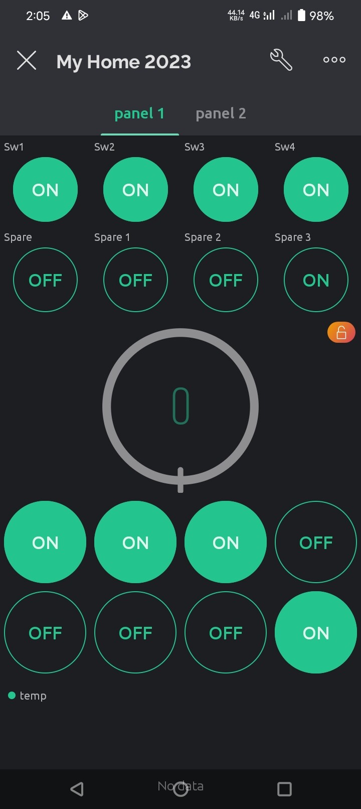
when I reset esp32, my output 1 which was high became low, my output 2 which was low became high.
/**********************************************************************************
 *  TITLE: ESP32 Home Automation project using Blynk | Internet & Manual control with Realtime Feedback | 8-CHANNEL RELAY
 *  Click on the following links to learn more.
 *  YouTube Video: https://youtu.be/o1e5s_5p3FU
 *  Related Blog : https://iotcircuithub.com/blynk-esp32-home-automation/
 *  by Tech StudyCell
 **********************************************************************************/
/*************************************************************
  Update the Preferences > Aditional boards Manager URLs:
  https://dl.espressif.com/dl/package_esp32_index.json, http://arduino.esp8266.com/stable/package_esp8266com_index.json

  Note: This requires ESP32 support package:
    https://github.com/espressif/arduino-esp32

  Download latest Blynk library here:
    https://github.com/blynkkk/blynk-library/releases/latest

 *************************************************************

  Change WiFi ssid, pass, and Blynk auth token to run :)

  Please be sure to select the right ESP32 module
  in the Tools -> Board menu!

 *************************************************************/
// Template ID, Device Name and Auth Token are provided by the Blynk.Cloud
// See the Device Info tab, or Template settings
#define BLYNK_TEMPLATE_ID ""
#define BLYNK_DEVICE_NAME ""
#define BLYNK_AUTH_TOKEN ""

// Comment this out to disable prints and save space
#define BLYNK_PRINT Serial

#include <WiFi.h>
#include <WiFiClient.h>
#include <BlynkSimpleEsp32.h>
#include <DHT.h>
#include <PCF8574.h>
#include <Wire.h>
#include <OneWire.h>
#include <DallasTemperature.h>
#define ONE_WIRE_BUS  15        // Your ESP8266 pin (ESP8266 GPIO 2 = WeMos D1 Mini pin D4)
OneWire oneWire(ONE_WIRE_BUS);
DallasTemperature sensors(&oneWire);

char auth[] = BLYNK_AUTH_TOKEN;

// Your WiFi credentials.
// Set password to "" for open networks.
char ssid[] = "";
char pass[] = "";

WidgetLED led1(V20);
WidgetLED led2(V21);
WidgetLED led3(V22);
WidgetLED led4(V23);
WidgetLED led5(V24);
WidgetLED led6(V25);
WidgetLED led7(V26);
WidgetLED led8(V27);

//Set i2c address
PCF8574 pcf8574(0x20);//input
PCF8574 pcf8574A(0x21);//output
PCF8574 pcf8574B(0x22);//output
PCF8574 pcf8574C(0x23);//input

BlynkTimer timer;

// define the GPIO connected with Relays and switches

// Input channel of PCF8574
#define PUSH_BUTTON_1    P0   //P0 PCF8574
#define PUSH_BUTTON_2    P1   //P1 PCF8574
#define PUSH_BUTTON_3    P2   //P2 PCF8574
#define PUSH_BUTTON_4    P3   //P3 PCF8574
#define PUSH_BUTTON_5    P4   //P4 PCF8574
#define PUSH_BUTTON_6    P5   //P5 PCF8574
#define PUSH_BUTTON_7    P6   //P6 PCF8574
#define PUSH_BUTTON_8    P7   //P7 PCF8574

// Output channel of PCF8574A
#define RELAY_PIN_1      P0  //P0 PCF8574A
#define RELAY_PIN_2      P1  //P1 PCF8574A
#define RELAY_PIN_3      P2  //P2 PCF8574A
#define RELAY_PIN_4      P3  //P3 PCF8574A
#define RELAY_PIN_5      P4  //P4 PCF8574A
#define RELAY_PIN_6      P5  //P5 PCF8574A
#define RELAY_PIN_7      P6  //P6 PCF8574A
#define RELAY_PIN_8      P7  //P7 PCF8574A

// Output channel of PCF8574B
#define RELAY_PIN_9      P0  //P0 PCF8574B
#define RELAY_PIN_10    P1  //P1 PCF8574B
#define RELAY_PIN_11    P2  //P2 PCF8574B
#define RELAY_PIN_12    P3  //P3 PCF8574B
#define RELAY_PIN_13    P4  //P4 PCF8574B
#define RELAY_PIN_14    P5  //P5 PCF8574B
#define RELAY_PIN_15    P6  //P6 PCF8574B
#define RELAY_PIN_16    P7  //P7 PCF8574B

// Input channel of PCF8574C
#define PUSH_BUTTON_9     P0   //P0 PCF8574C
#define PUSH_BUTTON_10   P1   //P1 PCF8574C
#define PUSH_BUTTON_11   P2   //P2 PCF8574C
#define PUSH_BUTTON_12   P3   //P3 PCF8574C
#define PUSH_BUTTON_13   P4   //P4 PCF8574C
#define PUSH_BUTTON_14   P5   //P5 PCF8574C
#define PUSH_BUTTON_15   P6   //P6 PCF8574C
#define PUSH_BUTTON_16   P7   //P7 PCF8574C


#define VPIN_BUTTON_1    V12
#define VPIN_BUTTON_2    V13
#define VPIN_BUTTON_3    V14
#define VPIN_BUTTON_4    V15
#define VPIN_BUTTON_5    V16
#define VPIN_BUTTON_6    V17
#define VPIN_BUTTON_7    V18
#define VPIN_BUTTON_8    V19
#define VPIN_BUTTON_9    V22
#define VPIN_BUTTON_10  V23
#define VPIN_BUTTON_11  V24
#define VPIN_BUTTON_12  V25
#define VPIN_BUTTON_13  V26
#define VPIN_BUTTON_14  V27
#define VPIN_BUTTON_15  V28
#define VPIN_BUTTON_16  V29


#define OTA_HOSTNAME "Home_Automation"

void checkPhysicalButton();

int relay1State = LOW;
int pushButton1State = HIGH;

int relay2State = LOW;
int pushButton2State = HIGH;

int relay3State = LOW;
int pushButton3State = HIGH;

int relay4State = LOW;
int pushButton4State = HIGH;

int relay5State = LOW;
int pushButton5State = HIGH;

int relay6State = LOW;
int pushButton6State = HIGH;

int relay7State = LOW;
int pushButton7State = HIGH;

int relay8State = LOW;
int pushButton8State = HIGH;

int relay9State = LOW;
int pushButton9State = HIGH;

int relay10State = LOW;
int pushButton10State = HIGH;

int relay11State = LOW;
int pushButton11State = HIGH;

int relay12State = LOW;
int pushButton12State = HIGH;

int relay13State = LOW;
int pushButton13State = HIGH;

int relay14State = LOW;
int pushButton14State = HIGH;

int relay15State = LOW;
int pushButton15State = HIGH;

int relay16State = LOW;
int pushButton16State = HIGH;


int wifiFlag =0;

int analogInput = A0; // 0-25v voltage sensor is connected with the analog pin A0 of the arduino

//For 0-25v voltage sensor
float correctionfactor = 3.8;
float vout = 0.0;
float vin = 0.0;

// two resistors 30K and 7.5k ohm
float R1 = 30000; // 30 k ohms resistor value connected to +5v
float R2 = 7500; // 7.5 k ohms resistor value connected to ground.
int value = 0;

#define wifiLed 2 // D2

#define DHTPIN 3 // What digital pin we're connected to

// Uncomment whatever type you're using!
//define DHTTYPE DHT11 // DHT11
#define DHTTYPE DHT22  // DHT22,AM2302,AM2321
//define DHTTYPE DHT21 // DHT21,AM2301

DHT dht(DHTPIN, DHTTYPE);

// This functiom sends Arduino's up time every second to Virtual Pin (5).
//In the app,Widget's reading frequency should be set PUSH.This means
//that you define how often to send data to Blynk App.


void sendSensor()
{
float h= dht.readHumidity();
float t= dht.readTemperature(); //or dht.readTemperature(true)for Fahrenheit

 //   if(isnan(h) || isnan(t)) {
 //   Serial.println("Failed to read from DHT sensor!");
 //   return;

value = analogRead(analogInput);
vout = (value * 5.0) / 1024; // see text
vin = vout / (R2/(R1+R2));
vin = vin - correctionfactor;

// You can send any value at any time.
// Please don't send more that 10 values per second.

Blynk.virtualWrite(V0, t);     // Virtual pin V0
Blynk.virtualWrite(V1, h);    // Virtual pin V1
Blynk.virtualWrite(V2, vin); // Virtual pin V2

}

// Input channel of PCF8574
#define PUSH_BUTTON_1    P0   //P0 PCF8574

// Output channel of PCF8574A
#define RELAY_PIN_1      P0  //P0 PCF8574A


#define VPIN_BUTTON_1    V12


BLYNK_CONNECTED() {

  // Request the latest state from the server

  Blynk.syncVirtual(VPIN_BUTTON_1);
  Blynk.syncVirtual(VPIN_BUTTON_2);
  Blynk.syncVirtual(VPIN_BUTTON_3);
  Blynk.syncVirtual(VPIN_BUTTON_4);
  Blynk.syncVirtual(VPIN_BUTTON_5);
  Blynk.syncVirtual(VPIN_BUTTON_6);
  Blynk.syncVirtual(VPIN_BUTTON_7);
  Blynk.syncVirtual(VPIN_BUTTON_8);
  Blynk.syncVirtual(VPIN_BUTTON_9);
  Blynk.syncVirtual(VPIN_BUTTON_10);
  Blynk.syncVirtual(VPIN_BUTTON_11);
  Blynk.syncVirtual(VPIN_BUTTON_12);
  Blynk.syncVirtual(VPIN_BUTTON_13);
  Blynk.syncVirtual(VPIN_BUTTON_14);
  Blynk.syncVirtual(VPIN_BUTTON_15);
  Blynk.syncVirtual(VPIN_BUTTON_16);

  // Alternatively, you could override server state using:
 // Blynk.virtualWrite(VPIN_BUTTON_1, relay1State);
 // Blynk.virtualWrite(VPIN_BUTTON_2, relay2State);
 // Blynk.virtualWrite(VPIN_BUTTON_3, relay3State);
 // Blynk.virtualWrite(VPIN_BUTTON_4, relay4State);
 // Blynk.virtualWrite(VPIN_BUTTON_5, relay5State);
 // Blynk.virtualWrite(VPIN_BUTTON_6, relay6State);
 // Blynk.virtualWrite(VPIN_BUTTON_7, relay7State);
 // Blynk.virtualWrite(VPIN_BUTTON_8, relay8State);
 // Blynk.virtualWrite(VPIN_BUTTON_9, relay9State);
 // Blynk.virtualWrite(VPIN_BUTTON_10, relay10State);
 // Blynk.virtualWrite(VPIN_BUTTON_11, relay11State);
 // Blynk.virtualWrite(VPIN_BUTTON_12, relay12State);
 // Blynk.virtualWrite(VPIN_BUTTON_13, relay13State);
 // Blynk.virtualWrite(VPIN_BUTTON_14, relay14State);
 // Blynk.virtualWrite(VPIN_BUTTON_15, relay15State);
 // Blynk.virtualWrite(VPIN_BUTTON_16, relay16State);


}


// When App button is pushed - switch the state

BLYNK_WRITE(VPIN_BUTTON_1) {
  relay1State = param.asInt();
  pcf8574A.digitalWrite(RELAY_PIN_1, relay1State);
Blynk.virtualWrite(V6,relay1State);
}

BLYNK_WRITE(VPIN_BUTTON_2) {
  relay2State = param.asInt();
  pcf8574A.digitalWrite(RELAY_PIN_2, relay2State);
Blynk.virtualWrite(V7,relay2State);
}

BLYNK_WRITE(VPIN_BUTTON_3) {
  relay3State = param.asInt();
  pcf8574A.digitalWrite(RELAY_PIN_3, relay3State);
Blynk.virtualWrite(V8,relay3State);
}

BLYNK_WRITE(VPIN_BUTTON_4) {
  relay4State = param.asInt();
  pcf8574A.digitalWrite(RELAY_PIN_4, relay4State);
Blynk.virtualWrite(V9,relay4State);
}

BLYNK_WRITE(VPIN_BUTTON_5) {
  relay5State = param.asInt();
  pcf8574A.digitalWrite(RELAY_PIN_5, relay5State);
Blynk.virtualWrite(V10,relay5State);
}

BLYNK_WRITE(VPIN_BUTTON_6) {
  relay6State = param.asInt();
  pcf8574A.digitalWrite(RELAY_PIN_6, relay6State);
Blynk.virtualWrite(V11,relay6State);
}

BLYNK_WRITE(VPIN_BUTTON_7) {
  relay7State = param.asInt();
  pcf8574A.digitalWrite(RELAY_PIN_7, relay7State);
Blynk.virtualWrite(V20,relay7State);
}

BLYNK_WRITE(VPIN_BUTTON_8) {
  relay8State = param.asInt();
  pcf8574A.digitalWrite(RELAY_PIN_8, relay8State);
Blynk.virtualWrite(V21,relay8State);
}

BLYNK_WRITE(VPIN_BUTTON_9) {
  relay9State = param.asInt();
  pcf8574B.digitalWrite(RELAY_PIN_9, relay9State);
Blynk.virtualWrite(V30,relay9State);
}

BLYNK_WRITE(VPIN_BUTTON_10) {
  relay10State = param.asInt();
  pcf8574B.digitalWrite(RELAY_PIN_10, relay10State);
Blynk.virtualWrite(V31,relay10State);
}

BLYNK_WRITE(VPIN_BUTTON_11) {
  relay11State = param.asInt();
  pcf8574B.digitalWrite(RELAY_PIN_11, relay11State);
Blynk.virtualWrite(V32,relay11State);
}

BLYNK_WRITE(VPIN_BUTTON_12) {
  relay12State = param.asInt();
  pcf8574B.digitalWrite(RELAY_PIN_12, relay12State);
Blynk.virtualWrite(V33,relay12State);
}

BLYNK_WRITE(VPIN_BUTTON_13) {
  relay13State = param.asInt();
  pcf8574B.digitalWrite(RELAY_PIN_13, relay13State);
Blynk.virtualWrite(V34,relay13State);
}

BLYNK_WRITE(VPIN_BUTTON_14) {
  relay14State = param.asInt();
  pcf8574B.digitalWrite(RELAY_PIN_14, relay14State);
Blynk.virtualWrite(V35,relay14State);
}

BLYNK_WRITE(VPIN_BUTTON_15) {
  relay15State = param.asInt();
  pcf8574B.digitalWrite(RELAY_PIN_15, relay15State);
Blynk.virtualWrite(V36,relay15State);
}

BLYNK_WRITE(VPIN_BUTTON_16) {
  relay16State = param.asInt();
  pcf8574B.digitalWrite(RELAY_PIN_16, relay16State);
Blynk.virtualWrite(V37,relay16State);
}


void checkPhysicalButton()
{
  if (pcf8574.digitalRead(PUSH_BUTTON_1) == LOW) {
    // pushButton1State is used to avoid sequential toggles
    if (pushButton1State != LOW) {

      // Toggle Relay state
      relay1State = !relay1State;
      pcf8574A.digitalWrite(RELAY_PIN_1, relay1State);
Blynk.virtualWrite(V6,relay1State);

     // Update Button Widget
      Blynk.virtualWrite(VPIN_BUTTON_1, relay1State);
    }
    pushButton1State = LOW;
  } else {
    pushButton1State = HIGH;
  }

if (pcf8574.digitalRead(PUSH_BUTTON_2) == LOW) {
    // pushButton2State is used to avoid sequential toggles
    if (pushButton2State != LOW) {

      // Toggle Relay state
      relay2State = !relay2State;
      pcf8574A.digitalWrite(RELAY_PIN_2, relay2State);
Blynk.virtualWrite(V7,relay2State);


      // Update Button Widget
      Blynk.virtualWrite(VPIN_BUTTON_2, relay2State);
    }
    pushButton2State = LOW;
  } else {
    pushButton2State = HIGH;
  }

 if (pcf8574.digitalRead(PUSH_BUTTON_3) == LOW) {
    // pushButton3State is used to avoid sequential toggles
    if (pushButton3State != LOW) {

      // Toggle Relay state
      relay3State = !relay3State;
      pcf8574A.digitalWrite(RELAY_PIN_3, relay3State);
Blynk.virtualWrite(V8,relay3State);


      // Update Button Widget
      Blynk.virtualWrite(VPIN_BUTTON_3, relay3State);
    }
    pushButton3State = LOW;
  } else {
    pushButton3State = HIGH;
  }

if (pcf8574.digitalRead(PUSH_BUTTON_4) == LOW) {
    // pushButton4State is used to avoid sequential toggles
    if (pushButton4State != LOW) {

      // Toggle Relay state
      relay4State = !relay4State;
      pcf8574A.digitalWrite(RELAY_PIN_4, relay4State);
Blynk.virtualWrite(V9,relay4State);


      // Update Button Widget
      Blynk.virtualWrite(VPIN_BUTTON_4, relay4State);
    }
    pushButton4State = LOW;
  } else {
    pushButton4State = HIGH;
  }

if (pcf8574.digitalRead(PUSH_BUTTON_5) == LOW) {
    // pushButton5State is used to avoid sequential toggles
    if (pushButton5State != LOW) {

      // Toggle Relay state
      relay5State = !relay5State;
      pcf8574A.digitalWrite(RELAY_PIN_5, relay5State);
Blynk.virtualWrite(V10,relay5State);


      // Update Button Widget
      Blynk.virtualWrite(VPIN_BUTTON_5, relay5State);
    }
    pushButton5State = LOW;
  } else {
    pushButton5State = HIGH;
  }

if (pcf8574.digitalRead(PUSH_BUTTON_6) == LOW) {
    // pushButton6State is used to avoid sequential toggles
    if (pushButton6State != LOW) {

      // Toggle Relay state
      relay6State = !relay6State;
      pcf8574A.digitalWrite(RELAY_PIN_6, relay6State);
Blynk.virtualWrite(V11,relay6State);


      // Update Button Widget
      Blynk.virtualWrite(VPIN_BUTTON_6, relay6State);
    }
    pushButton6State = LOW;
  } else {
    pushButton6State = HIGH;
  }

if (pcf8574.digitalRead(PUSH_BUTTON_7) == LOW) {
    // pushButton7State is used to avoid sequential toggles
    if (pushButton7State != LOW) {

      // Toggle Relay state
      relay7State = !relay7State;
      pcf8574A.digitalWrite(RELAY_PIN_7, relay7State);
Blynk.virtualWrite(V20,relay7State);


      // Update Button Widget
      Blynk.virtualWrite(VPIN_BUTTON_7, relay7State);
    }
    pushButton7State = LOW;
  } else {
    pushButton7State = HIGH;
  }

if (pcf8574.digitalRead(PUSH_BUTTON_8) == LOW) {
    // pushButton8State is used to avoid sequential toggles
    if (pushButton8State != LOW) {

      // Toggle Relay state
      relay8State = !relay8State;
      pcf8574A.digitalWrite(RELAY_PIN_8, relay8State);
Blynk.virtualWrite(V21,relay8State);


      // Update Button Widget
      Blynk.virtualWrite(VPIN_BUTTON_8, relay8State);
    }
    pushButton8State = LOW;
  } else {
    pushButton8State = HIGH;
  }

if (pcf8574C.digitalRead(PUSH_BUTTON_9) == LOW) {
    // pushButton9State is used to avoid sequential toggles
    if (pushButton9State != LOW) {

      // Toggle Relay state
      relay9State = !relay9State;
      pcf8574B.digitalWrite(RELAY_PIN_9, relay9State);
Blynk.virtualWrite(V30,relay9State);

     // Update Button Widget
      Blynk.virtualWrite(VPIN_BUTTON_9, relay9State);
    }
    pushButton9State = LOW;
  } else {
    pushButton9State = HIGH;
  }

 if (pcf8574C.digitalRead(PUSH_BUTTON_10) ==LOW) {
    // pushButton10State is used to avoid sequential toggles
    if (pushButton10State != LOW) {

      // Toggle Relay state
      relay10State = !relay10State;
     pcf8574B.digitalWrite(RELAY_PIN_10, relay10State);
Blynk.virtualWrite(V31,relay10State);


      // Update Button Widget
     Blynk.virtualWrite(VPIN_BUTTON_10, relay10State);
    }
    pushButton10State = LOW;
  } else {
    pushButton10State = HIGH;
  }

 if (pcf8574C.digitalRead(PUSH_BUTTON_11) ==LOW) {
    // pushButton11State is used to avoid sequential toggles
    if (pushButton11State != LOW) {

      // Toggle Relay state
      relay11State = !relay11State;
     pcf8574B.digitalWrite(RELAY_PIN_11, relay11State);
Blynk.virtualWrite(V32,relay11State);


      // Update Button Widget
     Blynk.virtualWrite(VPIN_BUTTON_11, relay11State);
    }
    pushButton11State = LOW;
  } else {
    pushButton11State = HIGH;
  }

if (pcf8574C.digitalRead(PUSH_BUTTON_12) == LOW) {
    // pushButton12State is used to avoid sequential toggles
    if (pushButton12State != LOW) {

      // Toggle Relay state
      relay12State = !relay12State;
     pcf8574B.digitalWrite(RELAY_PIN_12, relay12State);
Blynk.virtualWrite(V33,relay12State);


      // Update Button Widget
     Blynk.virtualWrite(VPIN_BUTTON_12, relay12State);
    }
    pushButton12State = LOW;
  } else {
    pushButton12State = HIGH;
  }

if (pcf8574C.digitalRead(PUSH_BUTTON_13) == LOW) {
    // pushButton13State is used to avoid sequential toggles
    if (pushButton13State != LOW) {

      // Toggle Relay state
      relay13State = !relay13State;
     pcf8574B.digitalWrite(RELAY_PIN_13, relay13State);
Blynk.virtualWrite(V34,relay13State);


      // Update Button Widget
     Blynk.virtualWrite(VPIN_BUTTON_13, relay13State);
    }
    pushButton13State = LOW;
  } else {
    pushButton13State = HIGH;
  }

if (pcf8574C.digitalRead(PUSH_BUTTON_14) == LOW) {
    // pushButton14State is used to avoid sequential toggles
    if (pushButton14State != LOW) {

      // Toggle Relay state
      relay14State = !relay14State;
     pcf8574B.digitalWrite(RELAY_PIN_14, relay14State);
Blynk.virtualWrite(V35,relay14State);


      // Update Button Widget
     Blynk.virtualWrite(VPIN_BUTTON_14, relay14State);
    }
    pushButton14State = LOW;
  } else {
    pushButton14State = HIGH;
  }

if (pcf8574C.digitalRead(PUSH_BUTTON_15) == LOW) {
    // pushButton15State is used to avoid sequential toggles
    if (pushButton15State != LOW) {

      // Toggle Relay state
      relay15State = !relay15State;
     pcf8574B.digitalWrite(RELAY_PIN_15, relay15State);
Blynk.virtualWrite(V36,relay15State);


      // Update Button Widget
     Blynk.virtualWrite(VPIN_BUTTON_15, relay15State);
    }
    pushButton15State = LOW;
  } else {
    pushButton15State = HIGH;
  }

if (pcf8574C.digitalRead(PUSH_BUTTON_16) == LOW) {
    // pushButton16State is used to avoid sequential toggles
    if (pushButton16State != LOW) {

      // Toggle Relay state
      relay16State = !relay16State;
     pcf8574B.digitalWrite(RELAY_PIN_16, relay16State);
Blynk.virtualWrite(V37,relay16State);


      // Update Button Widget
     Blynk.virtualWrite(VPIN_BUTTON_16, relay16State);
    }
    pushButton16State = LOW;
  } else {
    pushButton16State = HIGH;
  }

}


void checkBlynkStatus() { // called every 3 seconds by SimpleTimer

  bool isconnected = Blynk.connected();
  if(isconnected == false ){
    wifiFlag =1;
    digitalWrite(wifiLed,LOW);//Turn off Wifi LED
    }
  if (isconnected == true){
    wifiFlag =0;
    digitalWrite(wifiLed,HIGH);//Turn on Wifi LED
  }
}


void setup()
{

 // Debug console
  Serial.begin(115200);
  timer.setInterval(3000L, checkBlynkStatus); //check if Blynk server is connected every 3 seconds

  Blynk.begin(auth, ssid, pass);
  // You can also specify server:
  //Blynk.begin(auth, ssid, pass, "blynk.cloud", 80);
  //Blynk.begin(auth, ssid, pass, IPAddress(192,168,1,100), 8080);


// Set up a function to be called every second
   timer.setInterval(1000L,sendSensor);

  pinMode(analogInput, INPUT);
  pinMode(wifiLed,OUTPUT);

  pcf8574.pinMode(PUSH_BUTTON_1,INPUT_PULLUP);
  pcf8574.pinMode(PUSH_BUTTON_2,INPUT_PULLUP);
  pcf8574.pinMode(PUSH_BUTTON_3,INPUT_PULLUP);
  pcf8574.pinMode(PUSH_BUTTON_4,INPUT_PULLUP);
  pcf8574.pinMode(PUSH_BUTTON_5,INPUT_PULLUP);
  pcf8574.pinMode(PUSH_BUTTON_6,INPUT_PULLUP);
  pcf8574.pinMode(PUSH_BUTTON_7,INPUT_PULLUP);
  pcf8574.pinMode(PUSH_BUTTON_8,INPUT_PULLUP);
  pcf8574C.pinMode(PUSH_BUTTON_9,INPUT_PULLUP);
  pcf8574C.pinMode(PUSH_BUTTON_10,INPUT_PULLUP);
  pcf8574C.pinMode(PUSH_BUTTON_11,INPUT_PULLUP);
  pcf8574C.pinMode(PUSH_BUTTON_12,INPUT_PULLUP);
  pcf8574C.pinMode(PUSH_BUTTON_13,INPUT_PULLUP);
  pcf8574C.pinMode(PUSH_BUTTON_14,INPUT_PULLUP);
  pcf8574C.pinMode(PUSH_BUTTON_15,INPUT_PULLUP);
  pcf8574C.pinMode(PUSH_BUTTON_16,INPUT_PULLUP);


  pcf8574A.pinMode(RELAY_PIN_1, OUTPUT);
  pcf8574A.pinMode(RELAY_PIN_2, OUTPUT);
  pcf8574A.pinMode(RELAY_PIN_3, OUTPUT);
  pcf8574A.pinMode(RELAY_PIN_4, OUTPUT);
  pcf8574A.pinMode(RELAY_PIN_5, OUTPUT);
  pcf8574A.pinMode(RELAY_PIN_6, OUTPUT);
  pcf8574A.pinMode(RELAY_PIN_7, OUTPUT);
  pcf8574A.pinMode(RELAY_PIN_8, OUTPUT);
  pcf8574B.pinMode(RELAY_PIN_9, OUTPUT);
  pcf8574B.pinMode(RELAY_PIN_10, OUTPUT);
  pcf8574B.pinMode(RELAY_PIN_11, OUTPUT);
  pcf8574B.pinMode(RELAY_PIN_12, OUTPUT);
  pcf8574B.pinMode(RELAY_PIN_13, OUTPUT);
  pcf8574B.pinMode(RELAY_PIN_14, OUTPUT);
  pcf8574B.pinMode(RELAY_PIN_15, OUTPUT);
  pcf8574B.pinMode(RELAY_PIN_16, OUTPUT);


  pcf8574A.digitalWrite(RELAY_PIN_1,relay1State);
  pcf8574A.digitalWrite(RELAY_PIN_2,relay2State);
  pcf8574A.digitalWrite(RELAY_PIN_3,relay3State);
  pcf8574A.digitalWrite(RELAY_PIN_4,relay4State);
  pcf8574A.digitalWrite(RELAY_PIN_5,relay5State);
  pcf8574A.digitalWrite(RELAY_PIN_6,relay6State);
  pcf8574A.digitalWrite(RELAY_PIN_7,relay7State);
  pcf8574A.digitalWrite(RELAY_PIN_8,relay8State);
  pcf8574A.digitalWrite(RELAY_PIN_9,relay9State);
  pcf8574A.digitalWrite(RELAY_PIN_10,relay10State);
  pcf8574A.digitalWrite(RELAY_PIN_11,relay11State);
  pcf8574A.digitalWrite(RELAY_PIN_12,relay12State);
  pcf8574A.digitalWrite(RELAY_PIN_13,relay13State);
  pcf8574A.digitalWrite(RELAY_PIN_14,relay14State);
  pcf8574A.digitalWrite(RELAY_PIN_15,relay15State);
  pcf8574A.digitalWrite(RELAY_PIN_16,relay16State);

// Setup a function to be called every 100 ms
  timer.setInterval(500L, checkPhysicalButton);

  pcf8574.begin();  // push button
  pcf8574A.begin(); // relay A output
  pcf8574B.begin(); // relay B output
  pcf8574C.begin(); // push button


}

void loop()
{
 Blynk.run();
 timer.run();//Initiates Simple Timer
}