ESP is not responding. HELP

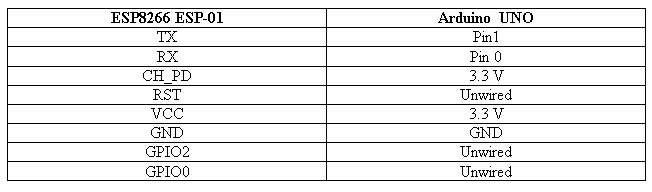
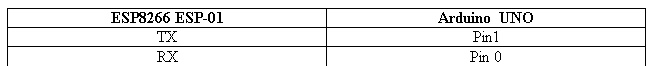
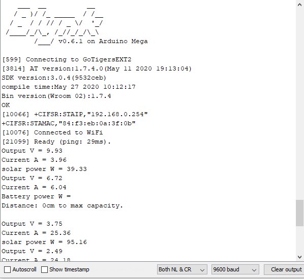
Can anyone please help with this? I’m using an Arduino Mega and Esp-01 for this project. My wifi module doesn’t seem to connect:

9] 
    ___  __          __
   / _ )/ /_ _____  / /__
  / _  / / // / _ \/  '_/
 /____/_/\_, /_//_/_/\_\
        /___/ v0.6.1 on Arduino Mega

[599] Connecting to Mike
[1609] ESP is not responding
#define BLYNK_PRINT Serial


#include <ESP8266_Lib.h>
#include <BlynkSimpleShieldEsp8266.h>

// You should get Auth Token in the Blynk App.
// Go to the Project Settings (nut icon).
char auth[] = "nli5lF1PNIgF0RFd3zhxYShPHKnvbsyU";

// Your WiFi credentials.
// Set password to "" for open networks.
char ssid[] = "Mike";
char pass[] = "THEw33kend";

// Hardware Serial on Mega, Leonardo, Micro...
#define EspSerial Serial1

// or Software Serial on Uno, Nano...
//#include <SoftwareSerial.h>
//SoftwareSerial EspSerial(2, 3); // RX, TX

// Your ESP8266 baud rate:
#define ESP8266_BAUD 38400

ESP8266 wifi(&EspSerial);
BlynkTimer timer;


int value = 0;
int adcValue = 0;
int sensitivity = 66;
int offsetVoltage = 2500;
double adcVoltage = 0;
double currentValue = 0;
double currentValueB = 0;
double power_solar = 0;
double power_Battery = 0;
int analogV = A3;
int analogI = A6;
int analogV_1 = A5;
int analogI_1 = A4;
float iout = 0.0;
float iin = 0.0;
float vout = 0.0;
float vin = 0.0;
float vin2 = 0.0;
float R1 = 10000.0; // resistance of R1 (100K) -see text!
float R2 = 3300.0; // resistance of R2 (10K) - see text!
float R3 = 10000.0; // resistance of R1 (100K) -see text!
float R4 = 4700.0; // resistance of R2 (10K) - see text!
int trigPin = 11;    // Trigger
int echoPin = 12;    // Echo
long duration, cm;
int relay_pump1 = 8;
int relay_pump2 = 9;
int relay_pump3 = 7;
int relay_reserve = 6;
void setup(){
  Serial.begin(9600);
  EspSerial.begin(ESP8266_BAUD);
  delay(10);

  Blynk.begin(auth, wifi, ssid, pass);
  pinMode(analogV, INPUT );
  pinMode(analogI, INPUT );
  pinMode(analogV_1, INPUT );
  pinMode(analogI_1, INPUT );
  pinMode(trigPin, OUTPUT);
  pinMode(echoPin, INPUT);
  
  timer.setInterval(10000, sendSensors);
  
}
void sendSensors(){
   //This sedtions deals of voltage sensor of solar
   value = analogRead(A3);
   vout = (value * 4.96) / 1023.0; // see text
   vin = vout / (R2/(R1+R2)); // Applying voltage divider rule
   
   // This section deals with the current sensor of solar
   adcValue=analogRead(A6);
   adcVoltage = (adcValue / 1023.0) * 5000;// read the value at analog input
   currentValue = - ((adcVoltage - offsetVoltage) / sensitivity); 
   power_solar = ( vin * currentValue); // For the power coming from the solar panel
   if (vin<0.09) { vin=0.0;  } //statement to quash undesired reading !

  // This section deals with battery voltage sensor
   value = analogRead(A5);
   vout = (value * 4.96) / 1023.0; // see text
   vin2 = vout / (R4/(R3+R4)); // Applying voltage divider rule
   
 //This section deals with battery current voltage 
   adcValue=analogRead(A4);
   adcVoltage = (adcValue / 1023.0) * 5000;// read the value at analog input
   currentValueB = - ((adcVoltage - offsetVoltage) / sensitivity); 
   power_Battery = ( vin2 * currentValueB); // For the power coming from the solar panel
   if (vin<0.09) { vin=0.0;  }         //statement to quash undesired reading !
    Serial.print("Output V = ");
    Serial.println(vin);
    
    Serial.print("Current A = ");
    Serial.println(currentValue);
    
    
    Serial.print("solar power W = ");
    Serial.println(power_solar);
    
    Serial.print("Output V = ");
    Serial.println(vin2);
    
    Serial.print("Current A = ");
    Serial.println(currentValueB);
    
    
    Serial.print("Battery power W = ");
    Serial.println();
    //Serial.println();

    digitalWrite(trigPin, LOW);
  delayMicroseconds(5);
  digitalWrite(trigPin, HIGH);
  delayMicroseconds(10);
  digitalWrite(trigPin, LOW);
 
  // Read the signal from the sensor: a HIGH pulse whose
  // duration is the time (in microseconds) from the sending
  // of the ping to the reception of its echo off of an object.
  pinMode(echoPin, INPUT);
  duration = pulseIn(echoPin, HIGH);
 
  // Convert the time into a distance
  cm = (duration/2) / 29.1;     // Divide by 29.1 or multiply by 0.0343
  Serial.print("Distance: ");
  Serial.print(cm);
  Serial.print("cm to max capacity.");
  Serial.println();
  Serial.println();
  Blynk.virtualWrite(V5, power_solar);
  Blynk.virtualWrite(V6, power_Battery);
    
  delay(3000);
}
void loop(){
  Blynk.run();
  timer.run();
}

Which pins on your Mega is the ESP-01 connected to?

This baud rate setting has to match the baud rate that your ESP-01 is expecting.
Therefore this either has to be the default baud rate setting for your module, or you need to have changed the ESP-01’s default baud rate via an AT command.

Pete.

1 Like

Thanks for the feedback I’ll try changing the baud rate via the AT command.

Or, you could just change your sketch to match the baud rate of your ESP.

Pete.

Just tried both, Still the same issue. I’ve already changed the baud rate of the ESP-01 and I’m able to get my IP address using the AT command but it’s still not responding when I upload my general code.

Many issues with connecting an ESP-01 to an Arduino… and solutions already posted for them all over the place in this forum :slight_smile: Search for keywords like ESP-01 and Mega :stuck_out_tongue:

Usual suspects are not powering the ESP-01 from its own 3.3v source (do not do so from the Arduino), not sharing the GND between power sources and not crossing the signal wires, TX to RX and vice versa

I don’t understand this comment.

Have you uploaded any code to the ESP-01, or is it still as it came out of the packet?

Try answering my original question about wiring…

Pete.

@PeteKnight
this is the format of my connection:

image

Yes, I have uploaded codes to the Esp-01.

You say Mega, then show us a hookup list to an UNO with totally different settings and pinouts than your sketch has… I think you need to clarify… and search more :stuck_out_tongue:

I will leave this topic alone now, as I have already answered all ESP-01 to Arduino questions many times before in this forum.

1 Like

Then that’s one of your problems.
The ESP-01 needs to be running AT firmware, and uploading a sketch to it overwrites that firmware. You need to re-install the AT firmware (which can’t be done via the Arduino IDE).
This might help you in that quest:

Your other problems are to do with this:
image

Your Arduino sketch says that you’ll be using Serial1 to communicate with your ESP-01…

Yet you’re connecting the ESP to Serial instead.
Serial1 on the Mega are pins 19 (Rx) and 18 (Tx).
In addition, the Tx on one device needs to connect to the Rx on the other and vice-versa, so it should look like this:

ESP-01 Tx ——> Mega pin 19
ESP-01 Rx ——> Mega pin 18

Pete.

3 Likes

Your Serial Monitor shows you are using Arduino Mega . . . But your table shows Arduino Uno . . . not the same pins . . .

Also . . .

If you have uploaded code to the ESP01 you have overwritten the AT firmware, it will not communicate with the UNO or MEGA . . .

As a test I used your sketch, with Arduino MEGA, with ESP-01 AT Firmware at 9600bd (I flash my ESP-01s to 9600bd as they are much more reliable at low speed) - strangely it would not work connected to Serial1 (Pins 18, 19) - but worked perfectly fine on Serial2 (pins 16, 17).

So your sketch is fine if you change to Serial2 - but you need to clarify if you have AT firmware or have overwritten it with custom code.

good luck
billd

3 Likes

Worked out why Serial1 did not work . . . the printing on the Mega board is reversed for RX1 and TX1, reversed the connection and it works fine . . .

cul
billd

1 Like

Alright, will give it a try today, getting a new Esp-01 module. I accidentally connected the one I had the 5v port. I think the circuit got fried and it’s not responding anymore. I’ll keep you posted on my progress once the new module arrives.

Alright, thanks a lot for this info. I’ll try this and give you feedback once I get my new Esp-01 module.

@PeteKnight @Bill_Donnelly I have a questio though, do I really need to flash an Esp-01 if I just got it?
I tried flashing my old Esp-01 module but it didn’t work. but from my Arduino serial monitor I was able to connect to the wifi on my phone.

No… not if you are using it as a WiFi interface for something else like an Arduino. Generally one only needs to reflash an ESP-01 with Arduino IDE/code if they want to use it as a standalone “mini” ESP8266 board.

Reflashing an ESP-01 back to the default AT firmware is usually done with seperate “firmware flashing” software… it has been awhile since I bothered with that, so you may need to Google for that yourself.

2 Likes

No, it should come flashed with the AT firmware - we only mentioned flashing because you said in your earlier post that you had

This implies you had overwritten the AT firmware on the ESP-01 with your own, but if you didn’t, then no need to re-flash with AT firmware.

billd

1 Like

Thank you!!

Noted.