Hi Blynk Community! I am having an error showing “ESP is not responding”. May I ask what I might have done wrong to cause this error? Thank you very much in advance! All the information is shown as follows:
Board: Arduino Mega
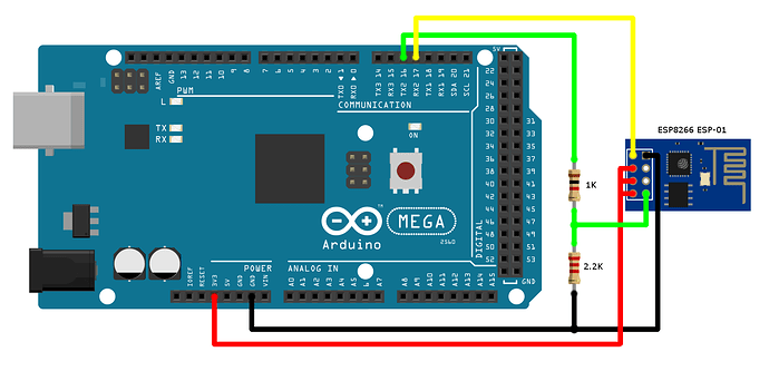
Wifi Module: ESP01
(ESP 01) AT version: v1.3.0.2
Blynk Library version: v1.0.1
Connection:
// I created 4 buttons in Blynk and wanna use these buttons to turn on LEDs using digital pins on Arduino Mega

#define BLYNK_TEMPLATE_ID "xxx"
#define BLYNK_DEVICE_NAME "xxx"
#define BLYNK_AUTH_TOKEN "xxx"

// Comment this out to disable prints and save space
#define BLYNK_PRINT Serial
#include <ESP8266_Lib.h>
#include <BlynkSimpleShieldEsp8266.h>

char auth[] = BLYNK_AUTH_TOKEN;

// Your WiFi credentials.
// Set password to "" for open networks.
char ssid[] = "xxx";
char pass[] = "xxx";

// Hardware Serial on Mega, Leonardo, Micro...
#define EspSerial Serial1

// Your ESP8266 baud rate:
#define ESP8266_BAUD 115200

ESP8266 wifi(&EspSerial);

// 1 LED Widget is blinking

BLYNK_WRITE(V1){

  //TOP LEFT OPTION
  int topLeftOpt = param.asInt();

  if(topLeftOpt == 0){
    Serial.println("Top Left LED: off");
    digitalWrite(22,LOW);
  }
  else{
    Serial.println("Top Left LED: on");
    digitalWrite(23,HIGH);
  }
}

BLYNK_WRITE(V2){

  //TOP RIGHT OPTION
  int topRightOpt = param.asInt();

  if(topRightOpt == 0){
    Serial.println("Top Right LED: off");
    digitalWrite(23,LOW);
  }
  else{
    Serial.println("Top Right LED: on");
    digitalWrite(23,HIGH);
  }
}

BLYNK_WRITE(V3){

  //BOTTOM LEFT OPTION
  int bottomLeftOpt = param.asInt();

  if(bottomLeftOpt == 0){
    Serial.println("Bottom Left LED: off");
    digitalWrite(12,LOW);
  }
  else{
    Serial.println("Bottom Left LED: on");
    digitalWrite(12,HIGH);
  }
}

BLYNK_WRITE(V4){

  //BOTTOM RIGHT OPTION
  int bottomRightOpt = param.asInt();

  if(bottomRightOpt == 0){
    Serial.println("Bottom Right LED: off");
    digitalWrite(13,LOW);
  }
  else{
    Serial.println("Bottom Right LED: on");
    digitalWrite(13,HIGH);
  }
}

void setup()
{
  pinMode(22,OUTPUT);
  pinMode(23,OUTPUT);
  pinMode(12,OUTPUT);
  pinMode(13,OUTPUT);
  Serial.begin(115200);

  // Set ESP8266 baud rate
  EspSerial.begin(ESP8266_BAUD);
  delay(10);

  Blynk.begin(auth, wifi, ssid, pass);

}

//In the loop function include Blynk.run() command.
void loop()
{
  Blynk.run();
}
Thank you so much for both of your advices @John93@distans! I tried the above wiring and connected the ESP01 to an external power supply but still the serial monitor is showing “ESP01 is not responding”. I even tried to use the wifi adapter module but it is still having the same problem. May I ask is there anything else I can try to fix this issue? Thank you so much and really appreciate for your time!
Sorry for not responding to that baud rate. I am sure the baud rate is 115200. I checked the serial monitor after flashing the ESP01.
Below is what I have tried but NOT working:
I tried both 9600 & 115200 baud rates in Arduino code.
I tried to use an external power supply that supplies 3.3V. The power supply that I used is a 12V1A power adapter, I connected it to a buck converter and stepped down the voltage to only 3.3V. The output voltage is checked using a multimeter.
I tried to use both 16 & 17 and 18 & 19 Arduino Mega pins to connect ESP01 TX & RX but both don’t work. The wiring is exactly the same as what @John93 suggested.
I tried to use an ESP01 serial wifi adapter module and connected it to the Arduino Mega board but the same error came out.
I tried to replace the ESP01 with a new one.
The ESP01 flashes blue light (+ constant red light) after I uploaded my code but just that the serial monitor is still showing “ESP01 is not responding”. I am connecting my Arduino Mega to lots of other components such as RFID, is there any chance that this might affect my WiFi connection? However, the good news is when I used RemoteXY instead of Blynk everything works out perfectly.
You need to clarify exactly what you are doing here.
What firmware are you flashing the ESP-01 with, and what software are you using to do this?
Why are you doing this at all?
What hardware are you using to flash your ESP-01 ?