Every opening curly bracket needs to have a corresponding closing curly bracket. Despite @John93 giving you a nicely formatted example of what your BLYNK_WRITE(V0) function should look like, you’ve butchered all of the indentations and omitted to copy the closing curly bracket.
Also, as you already have a void setup()' function, you just need to copy the pinMode()statement from John's example and paste it into your ownvoid setup()` without any additional curly brackets.
I’d also suggest that you place the pinMode() statement immediately after your Serial.begin() statement.
The rest of your void setup() is a mess though. These two lnes of code:
  WiFi.begin(ssid,pass);
  Blynk.config(auth);
should be removed, as the are not needed when you use Blynk.begin() and your Blynk.begin statement should actually look like this:
I’m really sorry with my low knowledge about code , this is the first project that i started with these kind of things. I’m really gladful if you guys can still help me here
I’ve updated my code like Pete said and i think i’m still wrong , it says expected initializer before ‘if’ . I really need the advice
//xx --
#define BLYNK_TEMPLATE_ID "TMPL***"
#define BLYNK_DEVICE_NAME "***"

#define BLYNK_PRINT Serial

#include <WiFi.h>
#include <WiFiClient.h>
#include <BlynkSimpleEsp32.h>

// kode yang dikirim aplikasi blynk ke email kalian.
// masukan kode yang sudah kalian copy di bawah.
char auth[] = "ysMxx";

// Your WiFi credentials.
// Set password to "" for open networks.
char ssid[] = "realxx"; ///NAMA WIFI ATAU HOTSPOT KALIAN
char pass[] = "tvjaqxx"; ///KATA SANDI WIFI ATAU HOTSPOT KALIAN
void setup()
{
  // Debug console
  Serial.begin(9600);

  pinMode(13, OUTPUT); // Initialise digital pin 2 as an output pin
  BLYNK_WRITE(V0) // Executes when the value of virtual pin 0 changes

  if(param.asInt() == 1) // execute this code if the switch widget is now ON
  digitalWrite(13,HIGH); // Set digital pin 2 HIGH
  else
   // execute this code if the switch widget is now OFF
  digitalWrite(13,LOW); // Set digital pin 2 LOW
 //Blynk.begin(auth, ssid, pass);
 Blynk.begin(auth, ssid, pass);

  }
void loop()
{
  Blynk.run();
}
//xx --
#define BLYNK_TEMPLATE_ID "TMPL***"
#define BLYNK_DEVICE_NAME "***"

#define BLYNK_PRINT Serial

#include <WiFi.h>
#include <WiFiClient.h>
#include <BlynkSimpleEsp32.h>

// kode yang dikirim aplikasi blynk ke email kalian.
// masukan kode yang sudah kalian copy di bawah.
char auth[] = "ysMxx";

// Your WiFi credentials.
// Set password to "" for open networks.
char ssid[] = "realxx"; ///NAMA WIFI ATAU HOTSPOT KALIAN
char pass[] = "tvjaqxx"; ///KATA SANDI WIFI ATAU HOTSPOT KALIAN

void setup()
{
  // Debug console
  Serial.begin(9600);
  pinMode(13, OUTPUT); // Initialise digital GPIO 13 as an output pin

 Blynk.begin(auth, ssid, pass);
 Blynk.connect();
}

void loop()
{
  Blynk.run();
}

BLYNK_WRITE(V0) { // Executes when the value of virtual pin 0 changes
  if (param.asInt() == 1) { // execute this code if the switch widget is now ON
    digitalWrite(13, HIGH); // Set digital pin 2 HIGH
  } else {
    // execute this code if the switch widget is now OFF
    digitalWrite(13, LOW); // Set digital pin 2 LOW
  }
}
Thank you so much @John93@PeteKnight@Blynk_Coeur it’s succesfully compiled. But when i connected to the things that i needed , it doesn’t work when i clicked the on or off button
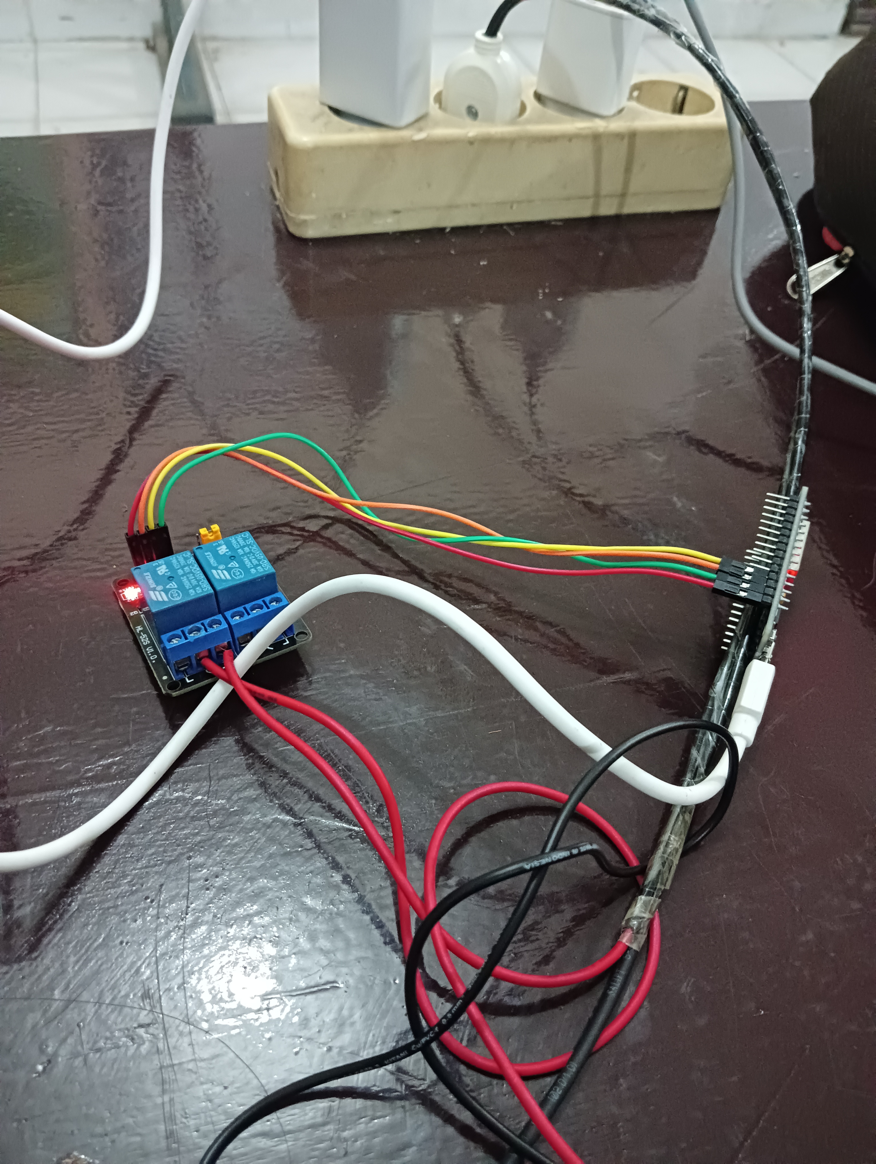
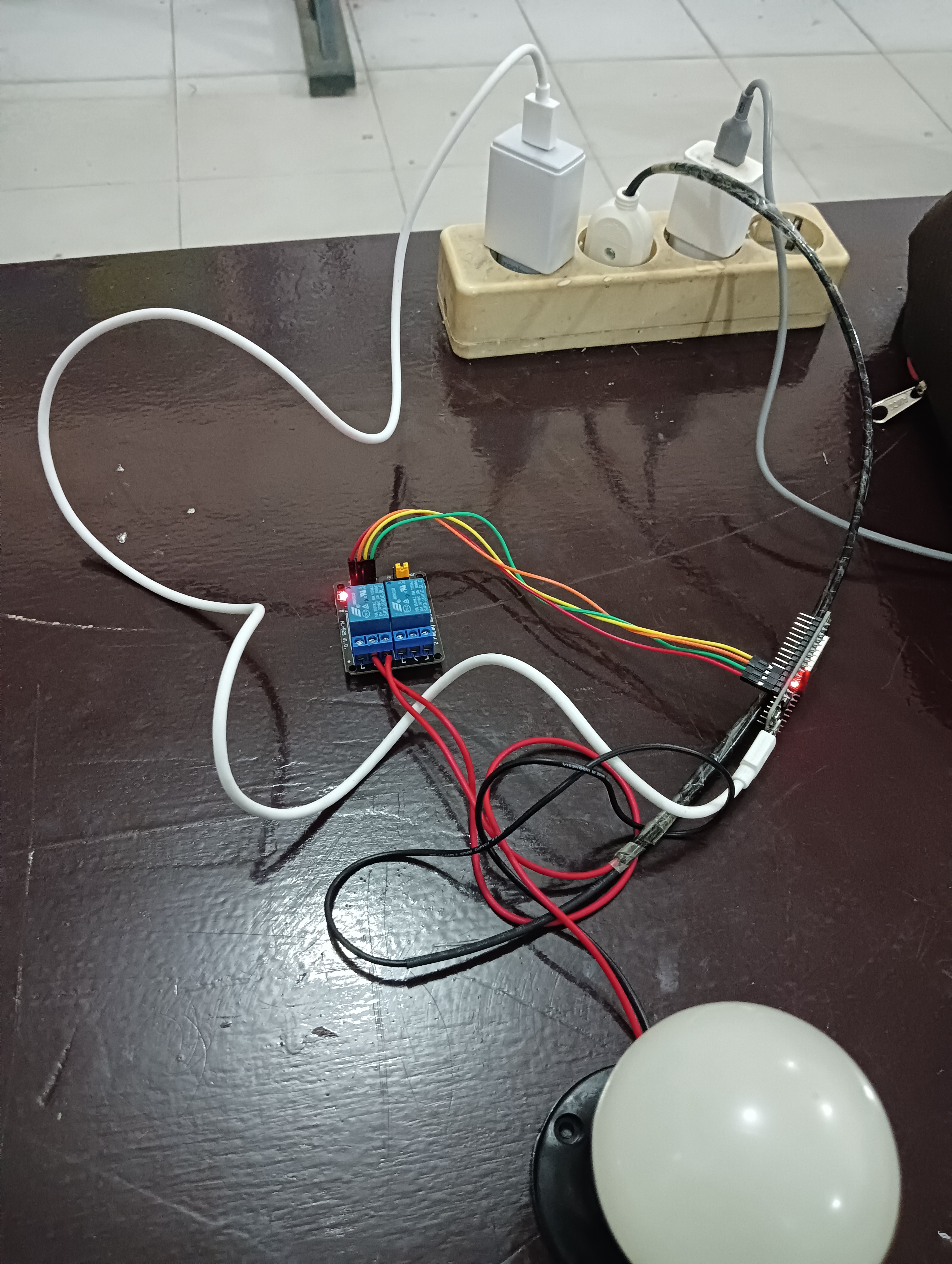
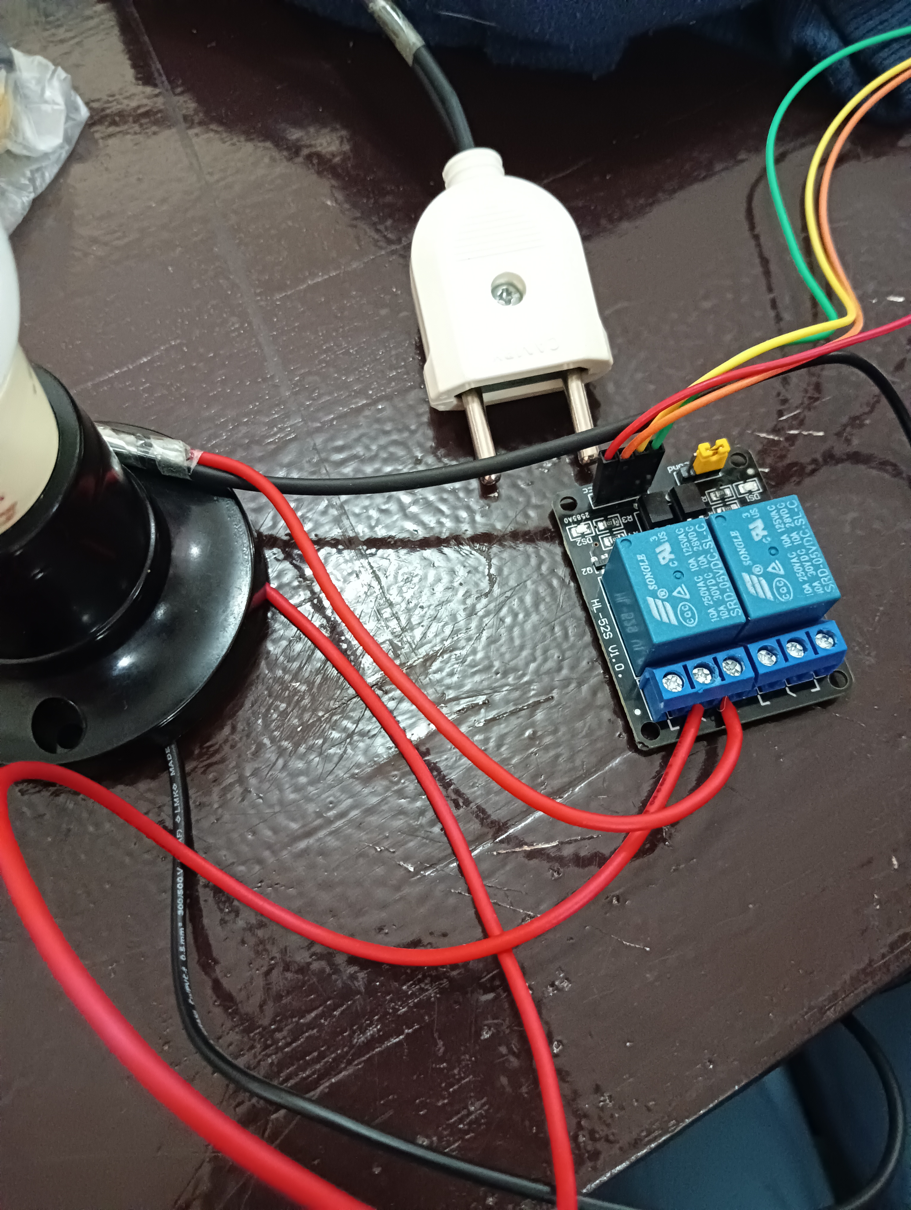
I used Relay with 2 channel 5 volt and a couple of cablea that connected to with the relay. And i used adaptor with 5v connected to esp32
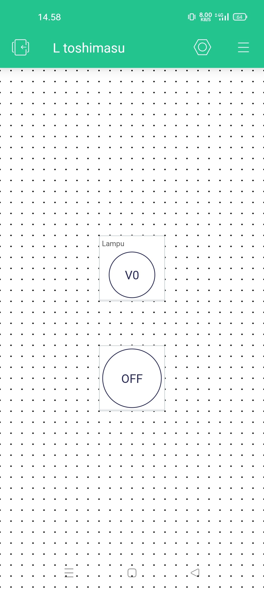
Your latest code only had one widget in the Blynk, app, connected to virtual datastream V0 and controlling pin GPIO13, so it will only control one of the relay channels.
That doesn’t tell us much about how you’ve wired-up and powered the relay board does it?
You probably need to post a wiring diagram and some photos to show your setup.
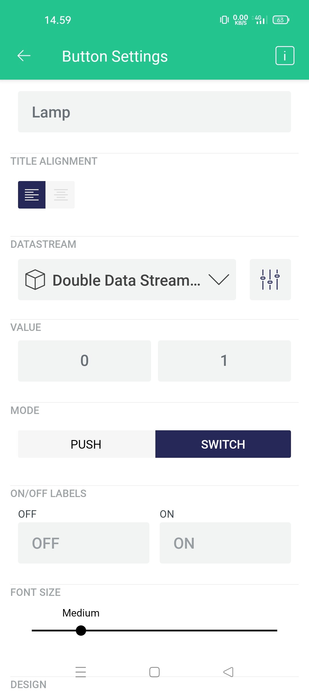
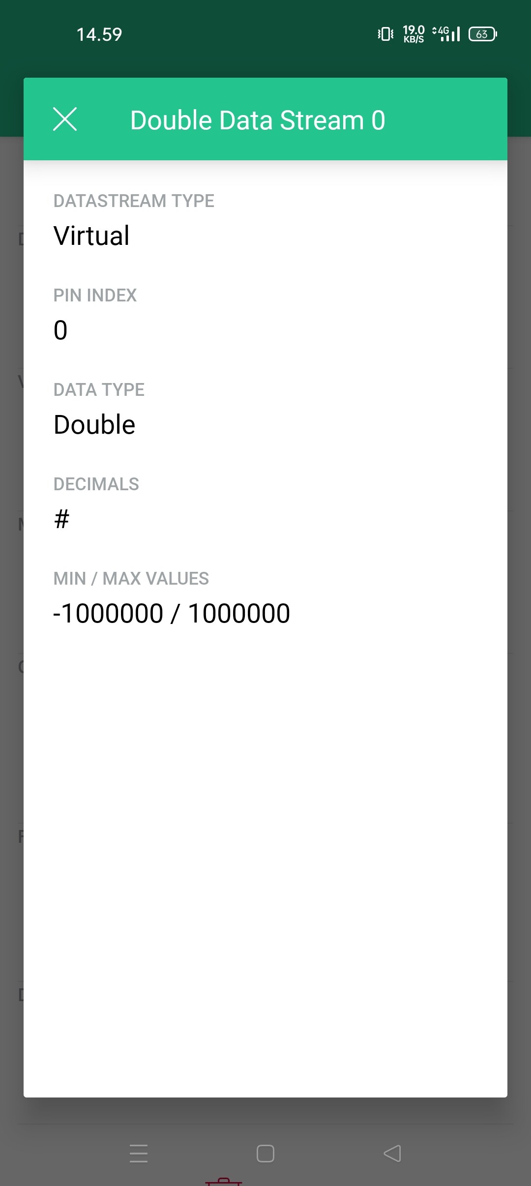
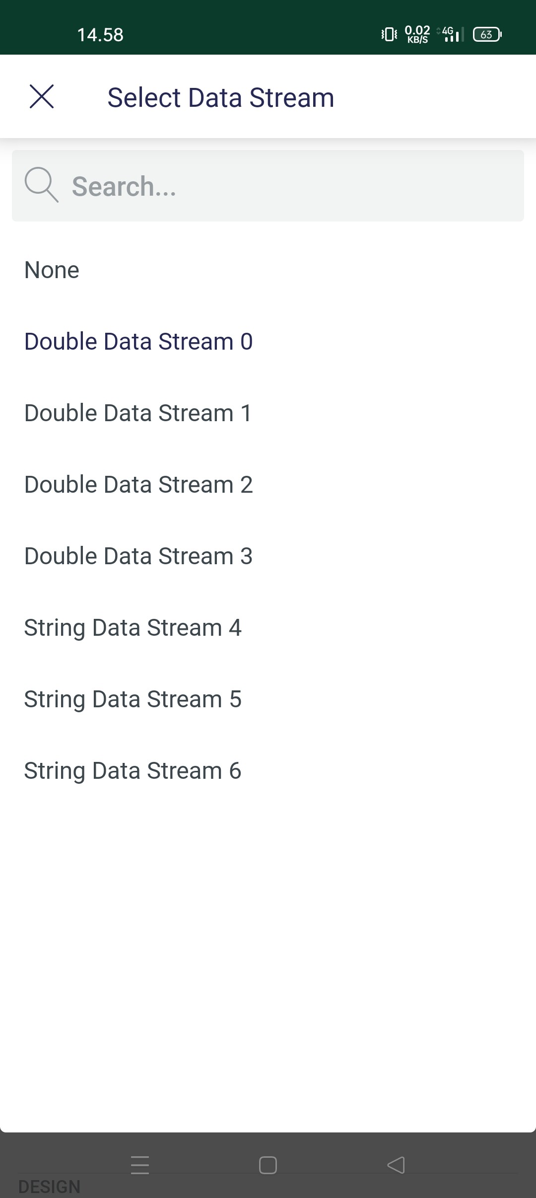
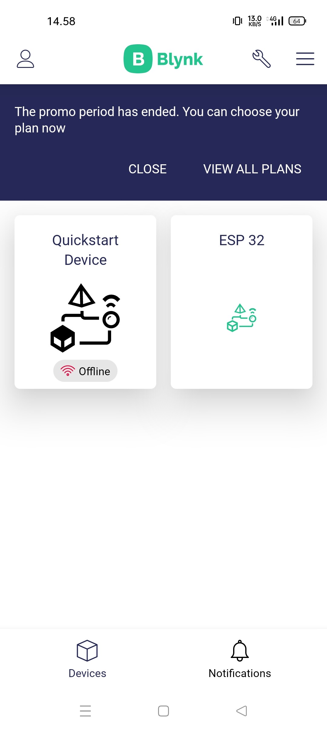
It would also be useful to know what you are seeing in your serial monitor, whether the device is showing as Online in Blynk, how you’ve set-up the button widget(s) in Blynk, and how you’ve configured your datastream(s).
Your virtual datastream should be an Integer data type, with a minimum of 0 and a maximum of 1.
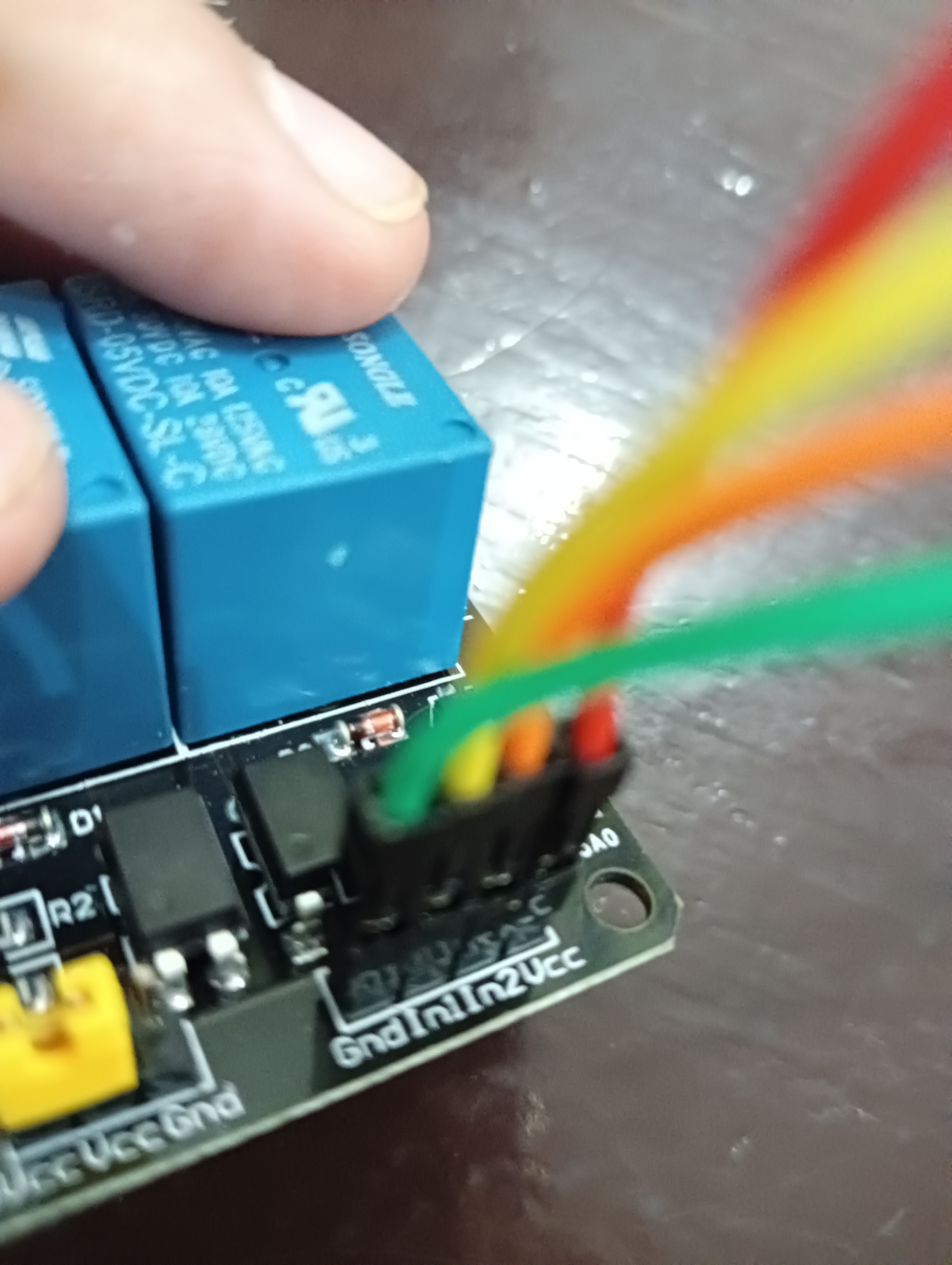
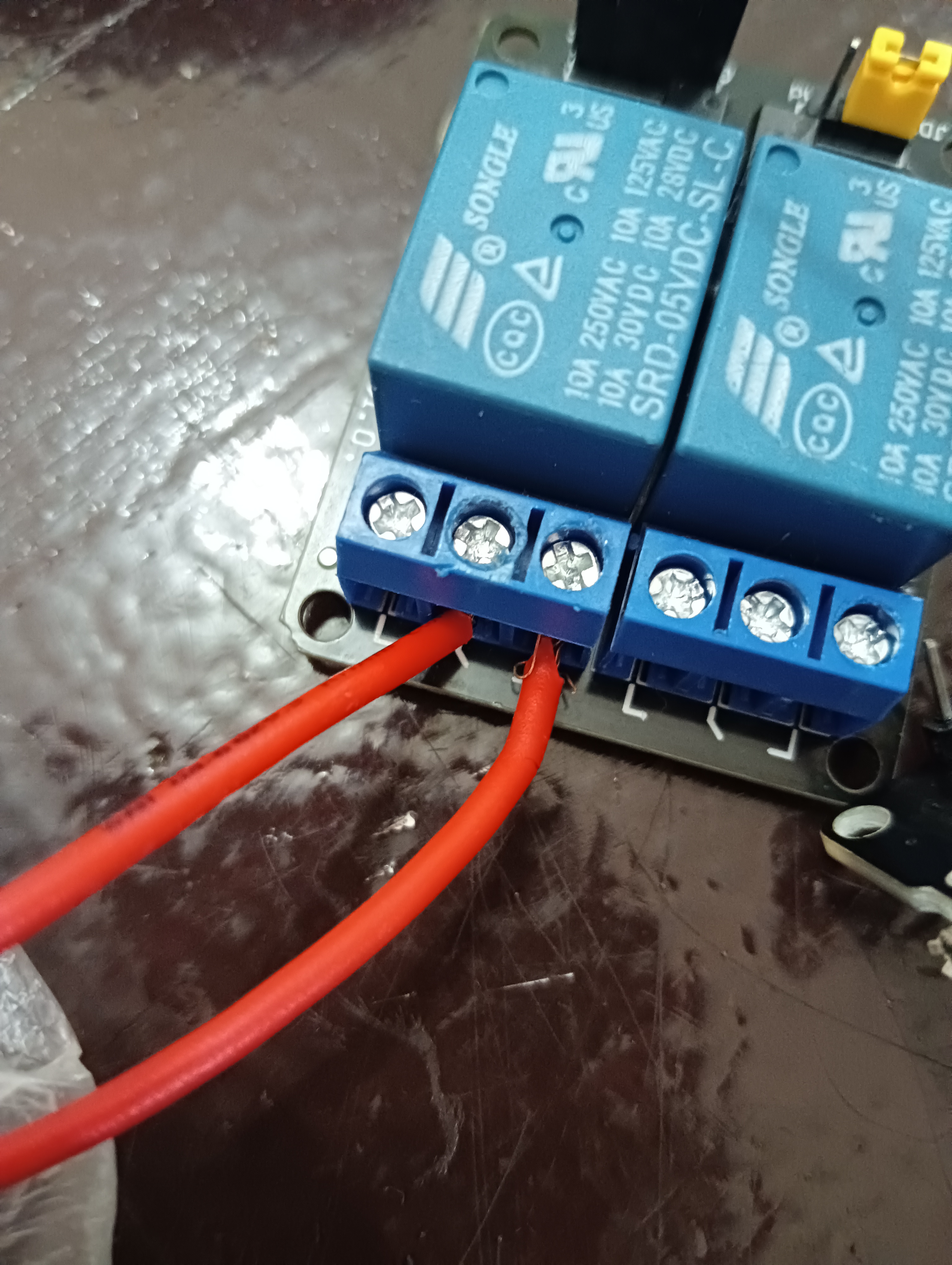
Your photos tell us nothing about which pins the four wires on the relay are connected to.
You haven’t answered any of my other questions. If you want help then you need to help us to help you, by providing sensible information and clear answers to questions.
The cables are connected to Ground , 1n2 , and Vcc at relay
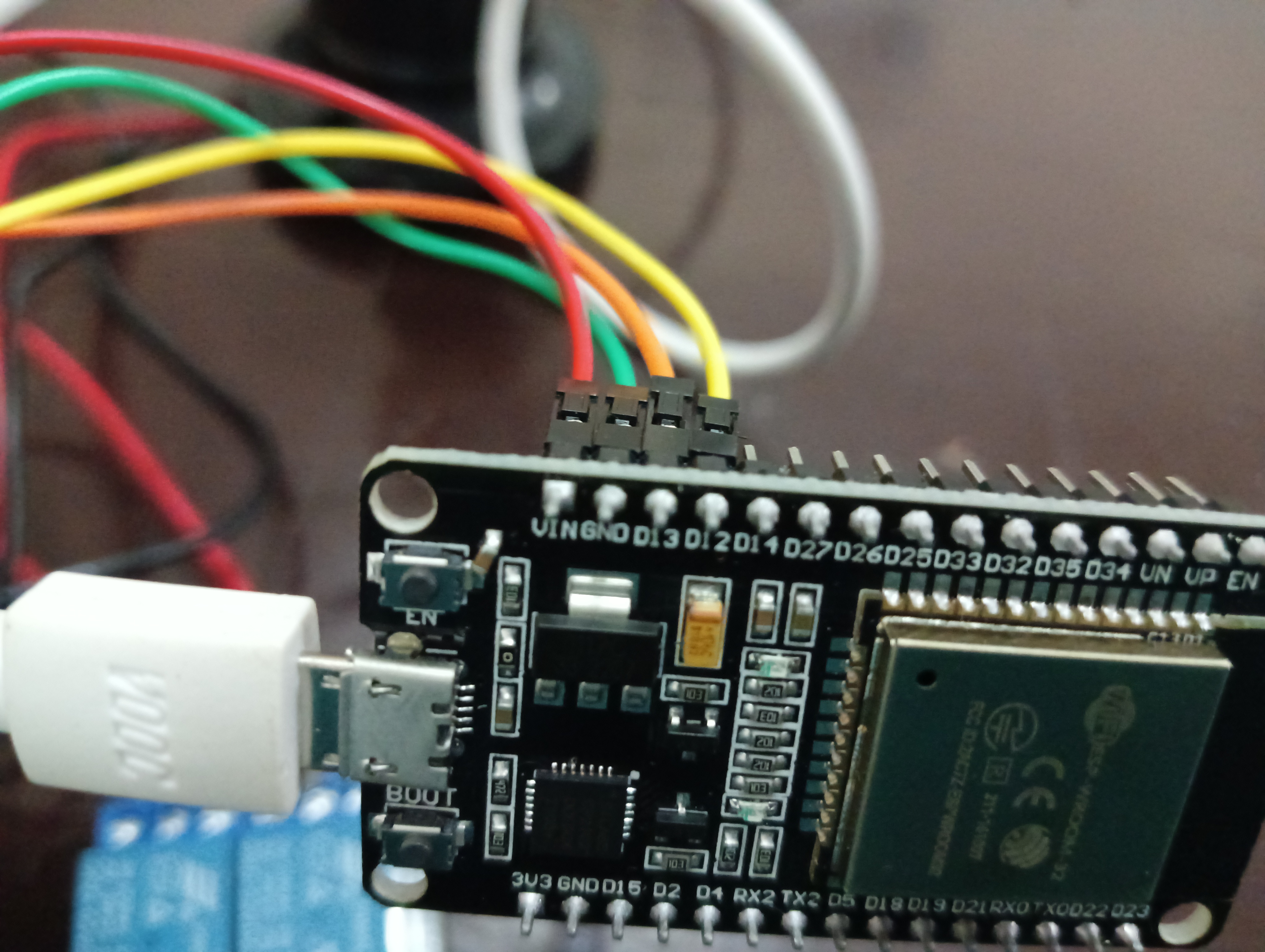
And at the esp it was Vin , Ground , D13 and D12 . I think we can just ignore the orange cable(D12) because it didn’t included in the code
I don’t have the the scheme picture and at the blynk app or website the esp said that the device was online . Sorry for the lack of informations
The V in is used as power input for the Esp32 and can’t be used as source for your relayboard.
You can use the 3.3V pin for that but your relayboard must also be 3.3V compatible…
Oh and most relayboards are low activated.
When you activate the widget switch, is the LED indicator for that relay on the relay board going on or off?
Is the relay clicking?
If you have access to a multimeter, is the GPIO13 pin going HIGH (3.3v) in relation to the GND pin when the switch widget is in the on position, and does it go LOW (0v in relation to GND) when the widget is off?
The relay you have is probably active LOW, so the relay will be energised when the switch widget is in the off position with your sketch as it currently stands, as your code is pulling the GPIO pin HIGH when the widget is on.
In that case, the low voltage side of things is working. If your light isn’t lighting-up then the problem is with the mains voltage side of things - either you’ve used the wrong contacts on the relay, or the bulb is faulty, or you’ve made some other wiring error on the mains voltage side.
Obviously it goes without saying that mains voltage can kill, so be careful with it.
When you get the light working, if the logic is reversed - it’s off when it should be on, then you’ll need to change your HIGH and LOW digitalWrite commands around to fix that, but get the light working first.
The bulb is worked, i’ve tested it before and i tested it again yesterday and it’s lighting up. The cables that connected to the relay is the one that from the plug and one from the light socket cable
Each relay has three connections - common, normally closed and normally open.
Are you using the correct connections?
If you have access to a multimeter you could test the relay output connections for resistance when actuated and not, to establish whether the relay is working correctly.
