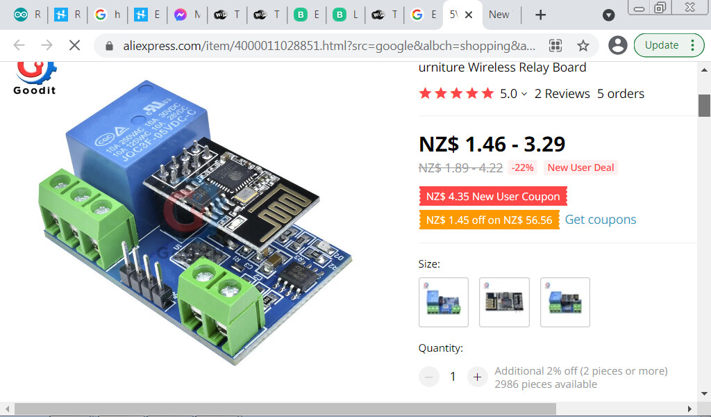
I have been trying to get a ESP-01 and HW-655 relay board. I understand that the serial code needs to be sent via the esp to another chip on the relay board
I have loaded the blink code that operates the relay using this serial information. Works fine
I have got Blynk talking to the ESP-01 and I can turn the blue LED on and off on GPIO1
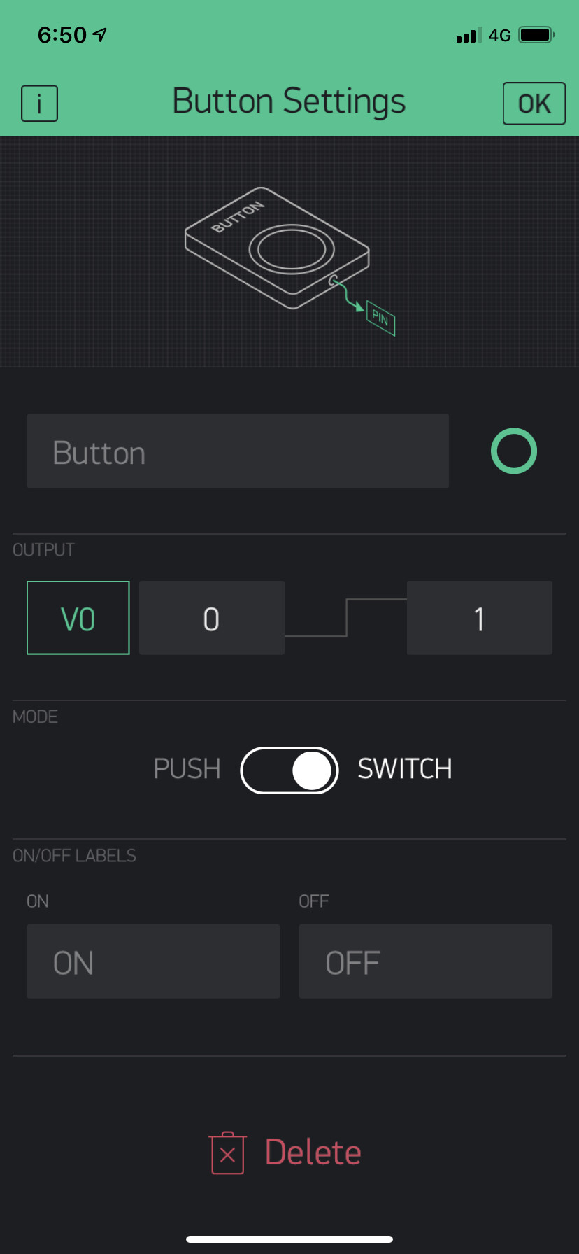
Tried using the Virtual pin to run the code to send the serial string. When I press the button on the IOS app nothing happens. The GPIO Pin will turn the LED on perfect.
I am sure I am missing something really simple but can not work it out.
I am using Blynk server and Blynk Library version 0.6.1
'/*control relay looking at virtual pin sent from Blynk and serial writing commands to chip onboard Relay board - works */
#define BLYNK_PRINT Serial

#include <ESP8266WiFi.h>
#include <BlynkSimpleEsp8266.h>

// You should get Auth Token in the Blynk App.
// Go to the Project Settings (nut icon).
char auth[] = "yourAuthToken";

// Your WiFi credentials.
// Set password to "" for open networks.
char ssid[] = "yourSSID";
char pass[] = "yourPassword";

byte relON[] = {0xA0, 0x01, 0x01, 0xA2}; //Hex command to send to serial for open relay
byte relOFF[] = {0xA0, 0x01, 0x00, 0xA1}; //Hex command to send to serial for close relay

void setup()
{
// Debug console
Serial.begin(9600);

Blynk.begin(auth, ssid, pass);
// You can also specify server: (Blynk sample code)
//Blynk.begin(auth, ssid, pass, "blynk-cloud.com", 8442);
//Blynk.begin(auth, ssid, pass, IPAddress(192,168,1,100), 8442);
}

// Relay on off
BLYNK_WRITE(V0) {
int button = param.asInt(); // read button
if (button == 1) {
Serial.write(relON, sizeof(relON));
}
else {
Serial.write(relOFF, sizeof(relOFF));
}
}

void loop()
{
Blynk.run();
}'
This Serial.begin command isn’t for the debug console, it’s for the communication with the “other chip”.
Some other code examples using this hardware use a baud rate of 115200 to communicate with the “other chip” and if this is the baud rate that it’s listening on then you’ll need to match this rate…
Thanks for the suggestion. Just tried that and no difference.
This is the communication to the relay that works without blynk
byte relOFF[] = {0xA0, 0x01, 0x00, 0xA1}; //Hex command to send to serial for close relay

int ledState = false;
unsigned long previousMillis = 0;
const long interval = 2000; //  2 seconds

// the setup function runs once when you press reset or power the board
void setup() {
 // initialize serial:
 Serial.begin(9600);
}

// the loop function runs over and over again forever
void loop()
{
 unsigned long currentMillis = millis();
 if(currentMillis - previousMillis >= interval) {
   previousMillis = currentMillis;
   if (ledState == true) {
     Serial.write(relON, sizeof(relON));     // turns the relay ON
     ledState = false;
   } else {
     Serial.write(relOFF, sizeof(relOFF));   // turns the relay OFF
     ledState = true;
   }
 }
}```
@flyonly please edit your post, using the pencil icon at the bottom, and add triple backticks at the beginning and end of your code so that it displays correctly.
Triple backticks look like this:
```
Added the LED into the subroutine to see if it was working. If I turn V0 on the LED does light up. Its like the BLYNK_WRITE(V0) is not sending the Serial.write
Also, GPIO1 on the ESP-01 is the Serial TX pin, so pulsing this with HIGH/LOW data bits will mess-up the serial communications.
Also, if you’ve added a pinMopde(1,OUTPUT) statement (which would be needed to turn the LED on/off via digitalWrite commands) then you need to remove it, as this will also corrupt the serial data communications.
Didn’t listen. Used GPIO0 and if the reed switch was closed when I energised the ESP-01 it would not connect to the wifi. Easy. Open the garage then power it on. This worked.
Then I thought I would take the suggestion. Moved it to GPIO2. It does the same thing.
 * *
 *   Magnetic switch
 *
 *   Blynk App project setup:
 *   LED widged attched to V4
 *
 *
 *
 **************************************************************/

#define BLYNK_PRINT Serial    // Comment this out to disable prints and save space
#include <ESP8266WiFi.h>
#include <BlynkSimpleEsp8266.h>

// You should get Auth Token in the Blynk App.
// Go to the Project Settings (nut icon).
char auth[] = "***************";

// Your WiFi credentials.
// Set password to "" for open networks.
char ssid[] = "***********";
char pass[] = "**********";

byte relON[] = {0xA0, 0x01, 0x01, 0xA2}; //Hex command to send to serial for open relay
byte relOFF[] = {0xA0, 0x01, 0x00, 0xA1}; //Hex command to send to serial for close relay


int StatMagSwitch = 0; // switch status setting to 0 or LOW initially, door closed
int PreviousStatus = 0; // this variable holds previous door status, 0: closed, 1: open

#define MAGPIN 2            // pin for magnetic switch

BlynkTimer timer;          // Initializing blynk

WidgetLED ledDoor(V4);     //Setting led widget as virtual pin 4 first
// This function sends Arduino's up time every second to Virtual Pins (4).
// In the app, Widget's reading frequency should be set to PUSH. This means
// that you define how often to send data to Blynk App

void sendReadings()
{ int DoorChanged = 0; // this variable will check whether door has changed, 1 if changed

  StatMagSwitch = digitalRead(MAGPIN);  // Reading Magnetic switch status

  if (StatMagSwitch != PreviousStatus)
  {
   DoorChanged = 1;
  }

  if (StatMagSwitch==1 && DoorChanged==1)
  {
    ledDoor.off(); //turning off if magnet is far away, i.e. Switch is HIGH
    Blynk.notify("Garage door just closed");
  }

  if (StatMagSwitch==0 && DoorChanged==1)
  {
    ledDoor.on(); //turning on if magnet is close, i.e. Switch is LOW
    Blynk.notify("Garage door just opened");
  }
  PreviousStatus = StatMagSwitch;

}

void setup()
{
  Serial.begin(9600); // See the connection status in Serial Monitor
  pinMode(MAGPIN, INPUT_PULLUP); // Defining magnetic switch pin as input_pullup
  Blynk.begin(auth, ssid, pass);

  // Setup a function to be called every second
  timer.setInterval(1000L, sendReadings);
}

// Relay on off
BLYNK_WRITE(V0) { int button = param.asInt(); // read button
  if (button == 1) {
  Serial.write(relON, sizeof(relON));
  }
  else { Serial.write(relOFF, sizeof(relOFF));
  }
}

void loop()
{
  Blynk.run(); // Initiates Blynk
  timer.run(); // Initiates SimpleTimer
}

The reed switch is NO when the garage door is open.
Okay, neither pin is really suitable for this, its just that GPIO2 is somewhat more suitable…
With your reed switch connected to GPIO2 and GND, and using an INPUT_PULLUP pinMode command, then I’d expect your device to boot correctly if the door is closed.
I think the problem is that you’re limiting your options by using this ESP-01 relay combo.
Do you actually need two relays to open/close your garage door?
The better solution may be a Wemos D1 Mini or NodeMCU.