I’m creating a project on blynk. It’s a communication system where I’m using the follwing:
- 2 arduino uno
- 2 NRF24L01 2.4GHz radio modules for communication between the arduinos
- 1 Grove SW-420 vibration sensor
One arduino (transmitting) has vibration sensor and one nrf module, and the other (receiving) has another nrf module and an LED. I’ve established communication between the two arduinos and when the vibration sensor senses vibration, it transmitts the intensity with some other data to the second arduino through the nrf transceiver. And this data is displayed on the serial monitor of the receiver module and the LED on pin2 blinks if vibration is sensed. Here is the ARDUINO IDE sketches of the Transmitter and Receiver that I wrote and work perfectly fine:
Transmitter:
#include "RF24.h"
#include "printf.h"
int EP = 2;
byte addresses[][6] = {"0"};


/* Hardware configuration: Set up nRF24L01 radio on SPI bus plus pins 7 & 8 */
RF24 radio(7, 8);


void setup() {
  pinMode(EP, INPUT); //set EP input for measurment
  Serial.begin(115200);
  delay(1000);
  radio.begin();
  radio.setChannel(115);
  radio.setPALevel(RF24_PA_LOW);
  radio.setDataRate( RF24_250KBPS ) ;
  radio.openWritingPipe( addresses[0]);
  delay(1000);
  Serial.println("----------------------Sender / Transmitter------------------------");
}

void loop() {
  long measurement = TP_init();
  delay(10);
  Serial.print("measurment = ");
  Serial.println(measurement);
    if (measurement > 100)
    {
      delay(200);
      // Send a message to rf95_server
      char data1[20] = {0};
      char data2[40]={0};
      char data3[200]={0};
      char data4[200]={0};
      snprintf(data1,20,"%d",measurement);
      snprintf(data2,40,"RTO No.: AS012021");
      snprintf(data3,200,"CUI:HyndaiElantra.5560@gmail.com");
      snprintf(data4,200,"Password: 55605560");
      radio.write(&data1, sizeof(data1));
      radio.write(&data2, sizeof(data2));
      radio.write(&data3, sizeof(data3));
      radio.write(&data4, sizeof(data4));
      delay(6000);

      //radio.waitPacketSent();
    }
    // Now wait for a reply
    uint8_t buf[32];
    uint8_t len = sizeof(buf);

    if (radio.available()) {
      while (radio.available()) radio.read(buf, len);
      Serial.print("got reply: ");
      Serial.println((char*)buf);
    } else {
    digitalWrite(8, LOW); // Assuming 'ss' is pin 8
    }
}

long TP_init() {
  delay(10);
  long measurement = pulseIn (EP, HIGH); //waits for the pin to get HIGH and returns measurement
  return measurement;
}
Receiver:
#include "RF24.h"
#include "printf.h"

/* Hardware configuration: Set up nRF24L01 radio on SPI bus plus pins 7 & 8 */
RF24 radio(7, 8);


byte addresses[][6] = {"0"};

int ledPin = 2;
int buzzer = 3;


void setup() {
  pinMode(ledPin, OUTPUT);
  pinMode(buzzer, OUTPUT);
  Serial.begin(115200);
  delay(1000);
  radio.begin();
  radio.setChannel(115);
  radio.setPALevel(RF24_PA_LOW);
  radio.setDataRate( RF24_250KBPS ) ;
  radio.openReadingPipe(1,addresses[0]);
  radio.startListening();
  Serial.println("   ---------------Assam (North-Eastern zone)--------------- \n ---------------Guwahati - Pole #1 (Khanapara)---------------");
}

void loop() {
  Serial.print("measurement = 0\n");
  if ( radio.available())
  {
    delay(200);
    // Should be a message for us now
    char buf1[20];
    uint8_t len1 = sizeof(buf1);
    char buf2[40];
    uint8_t len2 = sizeof(buf2);
    char buf3[200];
    uint8_t len3 = sizeof(buf3);
    char buf4[200];
    uint8_t len4 = sizeof(buf4);
    while (radio.available())
    {
      radio.read( &buf1, len1 );
      radio.read( &buf2, len2 );
      radio.read( &buf3, len3 );
      radio.read( &buf4, len4 );
      Serial.print("GOT VIBRATION: measurement= ");
        Serial.println((char*)buf1);
        Serial.println((char*)buf2);
        Serial.println((char*)buf3);
        Serial.println((char*)buf4);

        digitalWrite(ledPin, HIGH);
        tone(buzzer, 1200); // Send 1KHz sound signal...
        delay(250);        // ...for 1 sec
        digitalWrite(ledPin, LOW);
        noTone(buzzer);     // Stop sound...
        delay(250);        // ...for 1sec

    // Send a reply
        uint8_t data[] = "Thanks for the Data";
        radio.stopListening();
        radio.write(data, sizeof(data));
        radio.startListening();
        Serial.println("Sent a reply");

        digitalWrite(ledPin, LOW);
        digitalWrite(buzzer, LOW);
    }
  }
  delay(6000);

}
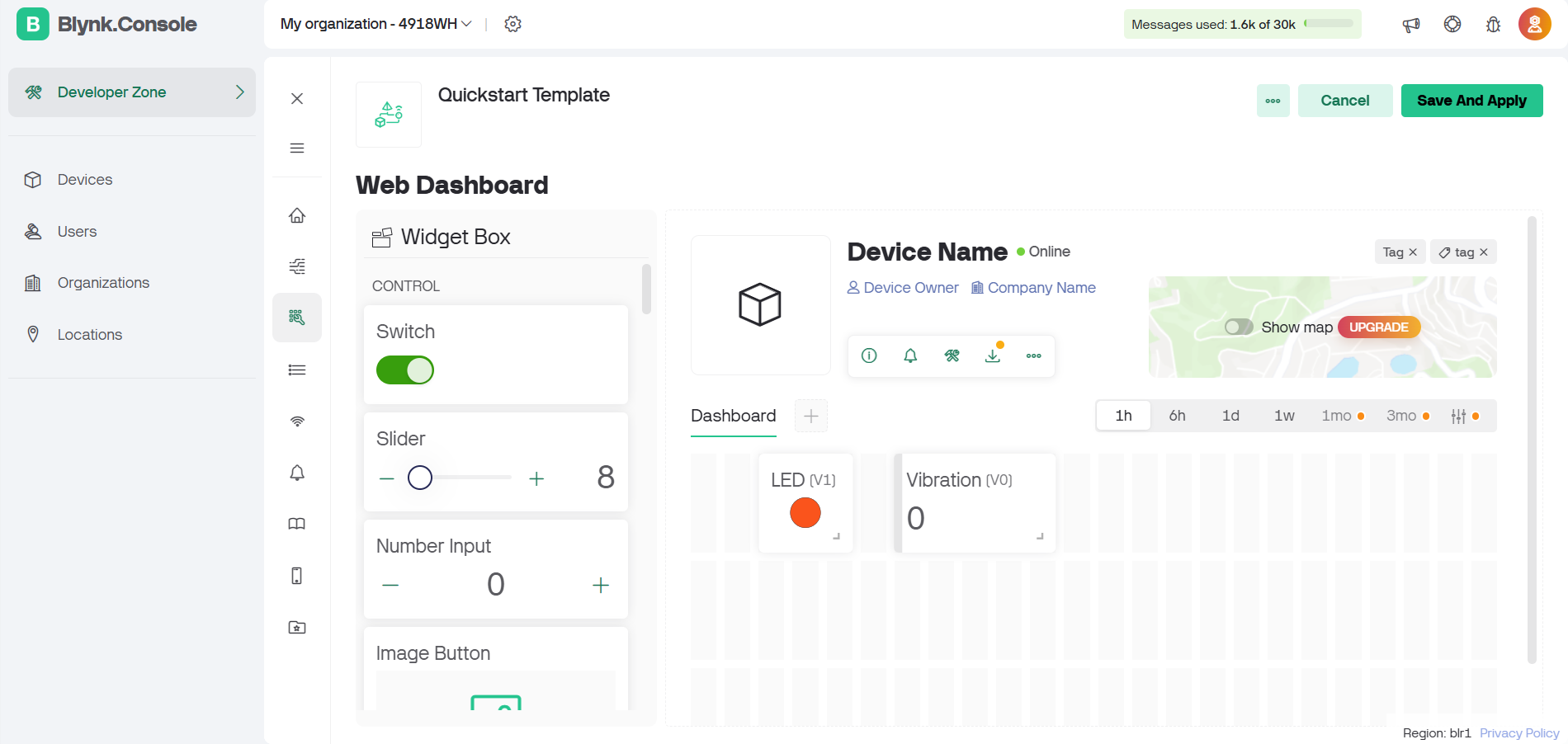
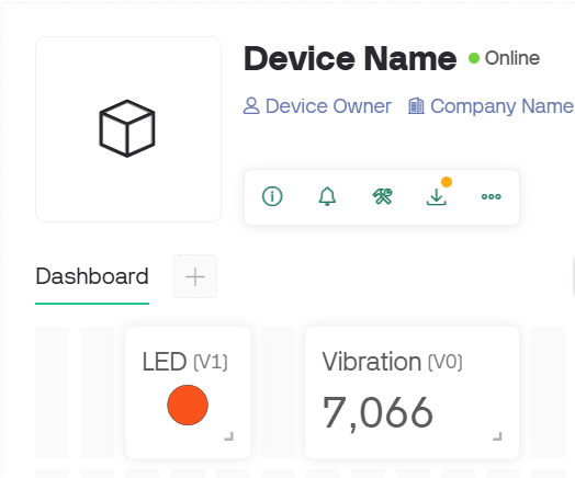
Now, actually I want to take vibration measurement data received by receiver arduino in variable buf1 and display that in blynk app. And also glow an LED on the app as and when a vibration is recorded. I’ve already checked my device with the app with an example and my device is getting online.
Till now, this is the code which I’ve written but neither LED is blinking nor Label is displaying measurement:
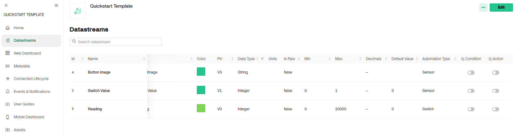
#define BLYNK_TEMPLATE_NAME         "Quickstart Template"
#define BLYNK_AUTH_TOKEN            "                                "
#include <SPI.h>
#include "RF24.h"
#include "printf.h"

/* Hardware configuration: Set up nRF24L01 radio on SPI bus plus pins 7 & 8 */
RF24 radio(7, 8);


byte addresses[][6] = {"0"};

int ledPin = 2;
int buzzer = 3;


#define BLYNK_PRINT SwSerial


#include <SoftwareSerial.h>
SoftwareSerial SwSerial(10, 11); // RX, TX

#include <BlynkSimpleStream.h>
WidgetLED led1(V1);


BlynkTimer timer;

void purpose()
{
  Serial.print("measurement = 0\n");
  if ( radio.available())
  {
    delay(200);
    // Should be a message for us now
    char buf1[20];
    uint8_t len1 = sizeof(buf1);
    char buf2[40];
    uint8_t len2 = sizeof(buf2);
    char buf3[200];
    uint8_t len3 = sizeof(buf3);
    char buf4[200];
    uint8_t len4 = sizeof(buf4);
    while (radio.available())
    {
      radio.read( &buf1, len1 );
      radio.read( &buf2, len2 );
      radio.read( &buf3, len3 );
      radio.read( &buf4, len4 );
      Serial.print("GOT VIBRATION: measurement= ");
        Serial.println((char*)buf1);
        Serial.println((char*)buf2);
        Serial.println((char*)buf3);
        Serial.println((char*)buf4);
        int mes=atoi(buf1);
        Blynk.virtualWrite(V0,mes);
        timer.setTimeout(0, []() { led1.on(); });
        timer.setTimeout(250L, []() { led1.off(); });
        digitalWrite(ledPin, HIGH);
        tone(buzzer, 1200); // Send 1KHz sound signal...
        delay(250);        // ...for 1 sec
        digitalWrite(ledPin, LOW);
        noTone(buzzer);     // Stop sound...
        delay(250);        // ...for 1sec

    // Send a reply
        uint8_t data[] = "Thanks for the Data";
        radio.stopListening();
        radio.write(data, sizeof(data));
        radio.startListening();
        Serial.println("Sent a reply");

        digitalWrite(ledPin, LOW);
        digitalWrite(buzzer, LOW);
    }
  }
  delay(6000);
}

void setup()
{
  pinMode(ledPin, OUTPUT);
  pinMode(buzzer, OUTPUT);
  // Debug console
  SwSerial.begin(115200);

  // Blynk will work through Serial
  // Do not read or write this serial manually in your sketch
  Serial.begin(9600);
  Blynk.begin(Serial, BLYNK_AUTH_TOKEN);
    // Setup a function to be called every second


  radio.begin();
  radio.setChannel(115);
  radio.setPALevel(RF24_PA_LOW);
  radio.setDataRate( RF24_250KBPS ) ;
  radio.openReadingPipe(1,addresses[0]);
  radio.startListening();
  timer.setInterval(1000L, purpose);
}

void loop()
{
  Blynk.run();
  timer.run();
  // You can inject your own code or combine it with other sketches.
  // Check other examples on how to communicate with Blynk. Remember
  // to avoid delay() function!
}
Someone kindly help me
OS: Windows 11
• Smartphone OS : Android 14
• Blynk Library 1.3.2