Displaying a Analog Value to Blynk APP via Virtual pins

Hi There, I’m new to blynk and just recently got my ESP8266 to blynk via an Arduino uno. Great work guys.

I’m busy with a project whereby I want to remotely with my phone monitor “Voltage” and “Current”. I used a opensource code and library from EmonLib and combined it with the Blynk code.

I want to add a Labeled Value on my Blynk APP to display the “Voltage” and “Current” which is read from my Arduino Uno on Analog pins 2 and 1 respectively. However the pin range can only be selected from over a range of 1023 for max 5V and this won’t suit me as the library does some involved calculations in the background for calibrations scaling etc.

How can I retrieve the values to display on the Blynk App. Meaning, for ex when I want to display a value on my LCD screen I simply type, lcd.print “Voltage”; or lcd.print “current”;

Is there a way using virtual pins whereby I can route the “Float Values” to the Blynk APP to display both “Voltage” and “Current” ?

Any help will be greatly appreciated. My Code thus far is shown below.


#include “EmonLib.h” // Include Emon Library
#define BLYNK_PRINT Serial // Comment this out to disable prints and save space
#include <ESP8266_Lib.h>
#include <BlynkSimpleShieldEsp8266.h>

// You should get Auth Token in the Blynk App.
// Go to the Project Settings (nut icon).
char auth[] = “--------”;

// Your WiFi credentials.
// Set password to “” for open networks.
char ssid[] = “--------”;
char pass[] = “--------”;

EnergyMonitor emon1; // Create an instance

#include <SoftwareSerial.h>
SoftwareSerial EspSerial(2, 3); // RX, TX

// Your ESP8266 baud rate:
#define ESP8266_BAUD 9600

ESP8266 wifi(&EspSerial);

void setup()
{
Serial.begin(9600);
delay(10);
// Set ESP8266 baud rate
EspSerial.begin(ESP8266_BAUD);
delay(10);
Blynk.begin(auth, wifi, ssid, pass);

emon1.voltage(2, 234.26, 1.7); // Voltage: input pin, calibration, phase_shift
emon1.current(1, 111.1); // Current: input pin, calibration.
}

void loop()
{
Blynk.run();
emon1.calcVI(20,2000); // Calculate all. No.of half wavelengths (crossings), time-out
emon1.serialprint(); // Print out all variables (realpower, apparent power, Vrms, Irms, power factor)

float realPower = emon1.realPower; //extract Real Power into variable
float apparentPower = emon1.apparentPower; //extract Apparent Power into variable
float powerFActor = emon1.powerFactor; //extract Power Factor into Variable
float supplyVoltage = emon1.Vrms; //extract Vrms into Variable
float Irms = emon1.Irms; //extract Irms into Variable
}

List item

Turn off value mapping and just assign a value to virtual pin

Thank you for your reply,

Sorry I’m quite new to this and not sure what you are referring to.

Is it really as simple as adding the code for ex. Blynk.virtualWrite (0, supplyVoltage); ?

Yes it is :slight_smile:

Excelent. Will try that. I didnt realise that you can actually turn off the value mapping in Blynk. Would teach me to read more detailed. Lol

Hi, So I’ve implemented the code my main program. Now I’m experiencing a new error.

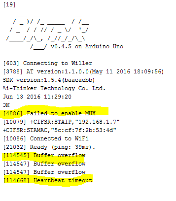
“Buffer Overflow” I think it may be the layout of my code…

Please Help.

Below messages from Serial Monitor

My Code:

#include <EmonLib.h>
#include <LiquidCrystal_I2C.h>
#define BLYNK_PRINT Serial // Comment this out to disable prints and save space
#include <ESP8266_Lib.h>
#include <BlynkSimpleShieldEsp8266.h>

char auth[] = “40ee80f235714637a967abd0cee2b6e2”;

char ssid[] = “Willer”;
char pass[] = “Willerpw@3590”;

#include <SoftwareSerial.h>
SoftwareSerial EspSerial(2, 3); // RX, TX

#define ESP8266_BAUD 9600

ESP8266 wifi(&EspSerial);

EnergyMonitor emon1; // Create an instance
LiquidCrystal_I2C lcd(0x27, 2, 1, 0, 4, 5, 6, 7, 3, POSITIVE);

void setup() {

// Set console baud rate
Serial.begin(9600);
delay(10);
// Set ESP8266 baud rate
EspSerial.begin(ESP8266_BAUD);
delay(10);

Blynk.begin(auth, wifi, ssid, pass);

lcd.begin(20, 4);
emon1.current(1, 111.1); // Current: input pin, calibration.
emon1.voltage(2, 271.00, 1.43); // Voltage: input pin, calibration, phase_shift
}
// the loop routine runs over and over again forever:
void loop() {

Blynk.run();

emon1.calcVI(20,2000); // Calculate all. No.of half wavelengths (crossings), time-out
float Irms = emon1.Irms; //extract Irms into Variable
float realPower = emon1.realPower; //extract Real Power into variable
float apparentPower = emon1.apparentPower; //extract Apparent Power into variable
float powerFActor = emon1.powerFactor; //extract Power Factor into Variable
float supplyVoltage = emon1.Vrms; //extract Vrms into Variable

lcd.setCursor(0,0);
lcd.print(supplyVoltage);
lcd.setCursor(0,1);
lcd.print(Irms);
lcd.setCursor(0,2);
lcd.print(apparentPower);
lcd.setCursor(0,3);
lcd.print(powerFActor + 0.07);
lcd.setCursor(6,0);
lcd.print(" V");
lcd.setCursor(6,1);
lcd.print(" A");
lcd.setCursor(6,2);
lcd.print(" VA");
lcd.setCursor(8,3);
lcd.print(“pF”);
delay(500);

Blynk.virtualWrite(0,supplyVoltage);
Blynk.virtualWrite(1,Irms);
Blynk.virtualWrite(2,apparentPower);

}

That’s correct. Ideally loop() should have 2 lines “Blynk” and SimpleTimer. Check the PushData example from the SKETCH BUILDER link at the top right of this page.

It gives you an insight how to schedule events with Blynk rather than your Arduino style loop() that is not compatible with Blynk.

That sorted the “Buffer Overflow” as well as “Mux Failed” error. However.

Won’t connect to Blynk App, Shows online for second, then goes offline

You should start with a sketch that does almost nothing like the PushData example and see if that stays connected to Blynk. Then move on from there by adding small parts of your required project and test after adding each part.

Ok I’ve done that. Code is running fine. lights is blynking. ma be a stupid question, but what result am I looking to get with Push data, on V5? I mapped it to a graph and constantly scrolls at 255

You need to learn to read the sketches.

“Value Display widget attached to V5”.

It will show uptime, updated every 1s, in the widget. Ensure it runs for 10 or 20 minutes and then move on with your project.

Just struggling to get my head around this “virtual” stuff.

I mapped the vale to a graph, Could see that its incrementing by one every second. I’ll take a break. Think my brain is fried by all the swotting up on the internet.

I’m learning as we go on, and at least its getting easier. Will carry on and report back.

Thanx for the assistance.

one more question for now.

Should I keep my program code separate from blynk code?

Meaning, create a “void main()” where my code will be?

No you don’t need your own void main() but you might need something like:

void function1(){
   // do something like update a virtual or physical LCD
}

void function2(){
    // do something else
}

I’ve come to the conclusion that its impossible to run the Blynk app through a esp8266 wifi module, while running a relatively straightforward code for the rest of your project.

I’ve tried separate functions, shuffled the code etc. It only runs flawlessly without adding the “heart” of my code.

, please help…

Willerpw, separate functions will get you halfway there. What you need is to use the simpletimer library, in order to allow for functioncalls “at the right time” as not to flood your esp device into resets.

You need to aim for a minimal loop() containing basically 2-3 lines

void loop()
{
    Blynk.run()
    timer.run()
}

Look at it this way. ESP8266 device has some internal stuff it needs to do before it gets to “your” code.
Alright so it has done its thing, then it goes to your loop.

First thing it does is hit Blynk.run()
This will make sure that your device is up to date on events transpired on your blynk android app, ie button presses etc has been handled. Of course you need to write some code for this part aswell with for example a button press on the app side needs to be handled on the ESP side by defining what that button press does.

BLYNK_WRITE(V0)
{
    // I PRESSED A BUTTON IN THE APP TO DO THIS ON MY ESP YAY
}

Now that you have allowed the ESP to do its internal thingamajigg aswell as allowed the Blynk library to do its thing (which in return also keeps you connected to the blynk server)

NOW comes the time for you to do “your” stuff outside of ESP and Blynk. If there is any, ie read sensors do functions bla bla. This is mostly done with timers, because the “loop” is very fast when you keep it simple and maybe you just dont need to do sensor readings every 10 milliseconds. So you add timers that call functions every 10 seconds maybe…

I hope this clears some for you…

TLDR;

  • Always keep your loop short, 2-3 lines including Blynk.run() and some type of timer.run()
  • When your setup part of your code is done the esp will work something like this
    ESP internal stuff -> Blynk stuff -> Timer stuff -> ESP internal stuff -> Blynk stuff -> Timer stuff etc
1 Like

I forgot to add the vital part.
If you block esps internal code for to long by using delays or long functions that take to much time, your device will reset.

Some goes for Blynk, but results in connection loss to the server.

This is absolutely not the case.
ESP’s are generally the best way to connect to Blynk and providing you follow a few rules (as outlined by @Fettkeewl) then you will have a trouble free project. Almost all WiFi signals drop at some point over a 12 month period but the great thing about Blynk and ESP’s the recovery is seamless (unlike many other connection methods).

Hi,

Thanks for your detailed explanation. I’ve managed to setup blynk using the push data example.
It’s been up and running for close to 24hr without loosing connection.

Integrating any other code to the Blynk example causes massive delays in data sending to the blynk server that it overload and I get buffer overloading errors. I’m trying to avoid having any other code except for the Blunk.run() and timer.run() in my void loop() but as soon as I add any code to it, the errors start, and connection to servers gets irradical.

@willerpw actually I notice from your OP that you are not using an ESP in standalone mode you are using the inferior connection method of adding an ESP to an Arduino.

Much of what has been written in this thread still holds true but you have to be even more careful when throwing an Arduino into the mix.