Time to update this topic with current status and code.
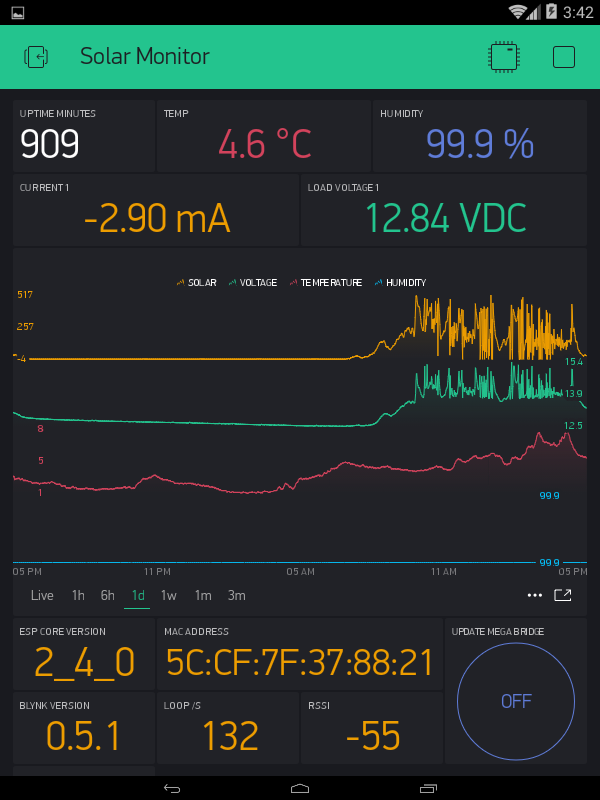
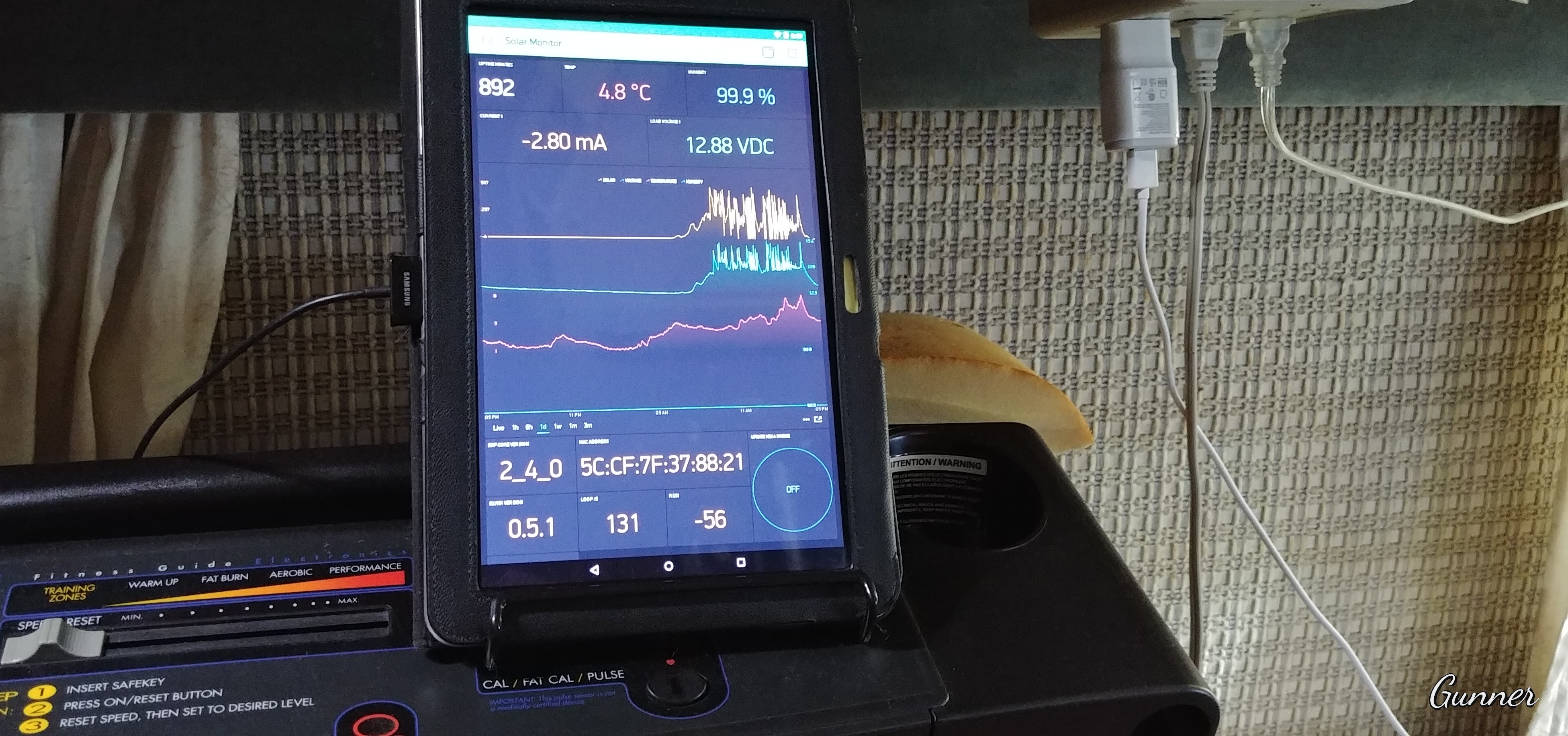
This system basically monitors a simple charge controller that is fed from a couple of solar panels wired in parallel. The App sits on my treadmill and “runs”  24/7 Giving me updates on charge rate, battery voltage, outside temperature & humidity (with a bridge feed to another bench-top project with indoor temp & humidity monitoring) and a history graph of the whole thing so i can look back a recollect how sunny but cold that there day was

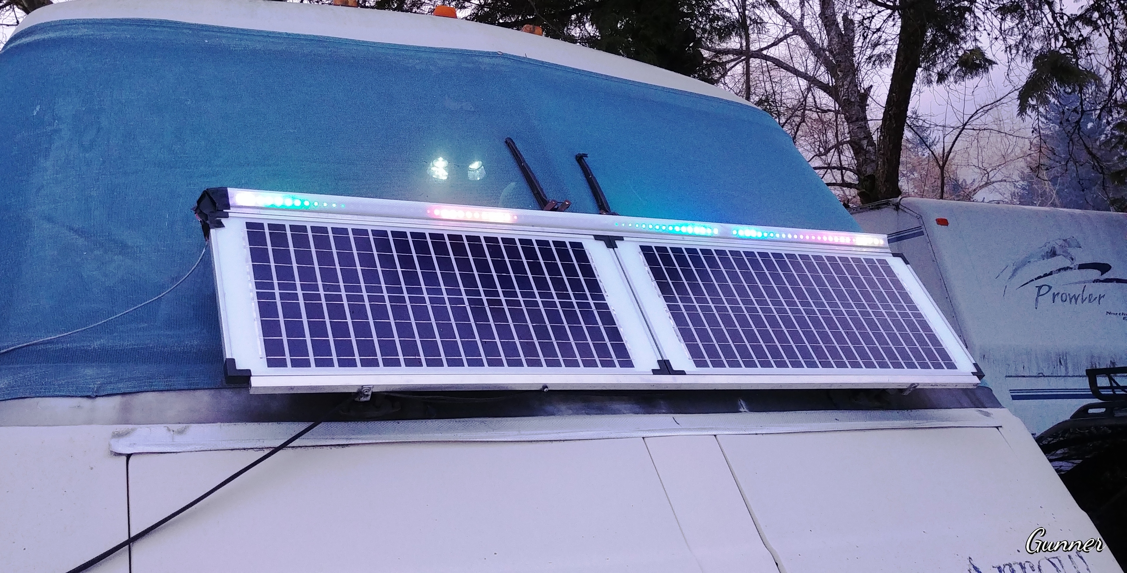
And since I also mounted a couple of 1.5 meter RGB strips on the solar panels - One facing outward and the other, wired in parallel, facing upwards to reflect on the windshield and thus inside. I figured I can have a single Wemos D1 Miini, doing multi-duty by controlling them as as well. It is running a FastLED scrolling demo, also 24/7.
I used to have the batteries power the LED strips, but since I doubled them up and let them run all night… these little batterys don’t have the holding power… so for now the LEDs are powered via as AC adapter.
#define BLYNK_MAX_READBYTES 1024
#define BLYNK_MSG_LIMIT 500
#define BLYNK_HEARTBEAT 60
#define BLYNK_NO_BUILTIN  // Disable built-in analog & digital pin operations

#include <ESP8266WiFi.h>  // For Blynk
#include <BlynkSimpleEsp8266.h>  // For Blynk

#include <DHT.h>  // For DHT22

#include <Wire.h>  // For INA219
#include <Adafruit_INA219.h>  // For INA219

#include <ESP8266mDNS.h>  // For OTA
#include <WiFiUdp.h>  // For OTA
#include <ArduinoOTA.h>  // For OTA

// ---------- For RGB Strip ----------
#include "FastLED.h"
FASTLED_USING_NAMESPACE
#if defined(FASTLED_VERSION) && (FASTLED_VERSION < 3001000)
#warning "Requires FastLED 3.1 or later; check github for latest code."
#endif
#define DATA_PIN 13
#define LED_TYPE WS2812
#define COLOR_ORDER GRB
#define NUM_LEDS 90
CRGB leds[NUM_LEDS];
#define BRIGHTNESS 100
#define FRAMES_PER_SECOND 120
#define LED_LIMIT_MILLIAMPS 3000 // Limit current in mA (Must be using FastLED v3.1.1+)
// -----------------------------------

BlynkTimer timer;
#define DHTPIN 0   // For DHT - GPIO0(D3) on Wemos D1 Mini - DHT22
#define DHTTYPE DHT22  // For DHT
DHT dht(DHTPIN, DHTTYPE);  // For DHT
float h, t;  // For DHT

Adafruit_INA219 ina219;  // For INA219 Current Sensor
float shuntvoltage = 0;  // For INA219 Current Sensor
float busvoltage = 0;  // For INA219 Current Sensor
float current_mA = 0;  // For INA219 Current Sensor
float loadvoltage = 0;  // For INA219 Current Sensor

char auth[] = "xxxxxxxxxx";
char ssid[] = "xxxxxxxxxx";
char pass[] = "xxxxxxxxxx";
char server[] = "xxx.xxx.xxx.xxx";
int port = 8080;

int CLK = 0;  // void loop() count variable

WidgetBridge bridge1(V43); //Initiating Bridge Widget - For Temp output to Mega


void setup() {
  dht.begin();  // For DHT

  uint32_t currentFrequency;  // For INA219 Current Sensor
  ina219.begin();  // For INA219 Current Sensor

  Blynk.connectWiFi(ssid, pass);
  Blynk.config(auth, server, port);
  Blynk.connect();

  // Timed Lambda Function - UpTime & void loop() cycle display
  timer.setInterval(1000L, []() {
    Blynk.virtualWrite(V0, millis() / 60000);
    Blynk.virtualWrite(V10, CLK);  // Display the void loop() cycles per second
    CLK = 0;  // Reset the void loop() cycles per second
  });  // END Timer Function

  // Timed Lambda Function - INA219 Current Sensor function
  timer.setInterval(1200L, []() {
    busvoltage = ina219.getBusVoltage_V();
    shuntvoltage = ina219.getShuntVoltage_mV();
    loadvoltage = busvoltage + (shuntvoltage / 1000);
    current_mA = ina219.getCurrent_mA();
    Blynk.virtualWrite(V4, current_mA);
    Blynk.virtualWrite(V3, busvoltage);
  });  // END Timer Function


  // Timed Lambda Function - RSSI display
  timer.setInterval(4500L, []() {
    Blynk.virtualWrite(V9, WiFi.RSSI());
  });  // END Timer Function

  // Timed Lambda Function - DHT22 Temp & Humidity sensor
  timer.setInterval(62200L, []() {
    h = dht.readHumidity();
    t = dht.readTemperature(); // or dht.readTemperature(true) for Fahrenheit
    // Check if any reads failed and try again.
    if (isnan(h) || isnan(t)) {
      delay(600);
      h = dht.readHumidity();
      t = dht.readTemperature(); // or dht.readTemperature(true) for Fahrenheit
    }
    Blynk.virtualWrite(V7, h);
    Blynk.virtualWrite(V8, t);
  });  // END Timer Function

  // Timer for MEGA Bridge Data Dump Function
  timer.setInterval(63000L, MEGAupdate);  // Sending bridge data to MEGA

  ArduinoOTA.setHostname("Wemos D1 Mini Solar Monitor - Fast LED RGB");  // For OTA
  ArduinoOTA.begin();  // For OTA

  // FastLED LED strip configuration
  FastLED.addLeds<LED_TYPE, DATA_PIN, COLOR_ORDER>(leds, NUM_LEDS).setCorrection(TypicalLEDStrip);
  FastLED.setBrightness(BRIGHTNESS);  // set master brightness control
}  // END Setup Loop


BLYNK_CONNECTED() {
  bridge1.setAuthToken("d1e516ca1d8b4d57a172dac786907a90"); // Token for the Mega
  Blynk.virtualWrite(V0, "REBOOT");
  Blynk.virtualWrite(V5, WiFi.macAddress());
  Blynk.virtualWrite(V11, ESP.getCoreVersion());
  Blynk.virtualWrite(V12, BLYNK_VERSION);
}


BLYNK_WRITE(V6) {
  if (param.asInt()) {
    MEGAupdate();
  }
}

void MEGAupdate() { //  Sending data to MEGA
  bridge1.virtualWrite(V43, t);
  bridge1.virtualWrite(V44, h);
  bridge1.virtualWrite(V47, current_mA);
  bridge1.virtualWrite(V48, busvoltage);
}


// List of patterns to cycle through.  Each is defined as a separate function below.
typedef void (*SimplePatternList[])();
SimplePatternList gPatterns = { rainbow, rainbowWithGlitter, confetti, sinelon, juggle, bpm };
uint8_t gCurrentPatternNumber = 0; // Index number of which pattern is current
uint8_t gHue = 0; // rotating "base color" used by many of the patterns
#define ARRAY_SIZE(A) (sizeof(A) / sizeof((A)[0]))


void loop() {
  CLK++;  // Count the void loop() cycles per second
  Blynk.run();
  timer.run();
  ArduinoOTA.handle();  // For OTA

  gPatterns[gCurrentPatternNumber](); // Call the current pattern function once, updating the 'leds' array
  FastLED.show();  // send the 'leds' array out to the actual LED strip
  FastLED.delay(500 / FRAMES_PER_SECOND);  // insert a delay to keep the framerate modest

  // do some periodic updates
  EVERY_N_MILLISECONDS( 20 ) {
    gHue++;  // slowly cycle the "base color" through the rainbow
  }

  EVERY_N_SECONDS( 10 ) {
    nextPattern();  // change patterns periodically
  }
}  // END Void loop


void nextPattern() {
  // add one to the current pattern number, and wrap around at the end
  gCurrentPatternNumber = (gCurrentPatternNumber + 1) % ARRAY_SIZE( gPatterns);
}

void rainbow() {
  // FastLED's built-in rainbow generator
  fill_rainbow( leds, NUM_LEDS, gHue, 7);
}

void rainbowWithGlitter() {
  // built-in FastLED rainbow, plus some random sparkly glitter
  rainbow();
  addGlitter(80);
}

void addGlitter( fract8 chanceOfGlitter) {
  if ( random8() < chanceOfGlitter) {
    leds[ random16(NUM_LEDS) ] += CRGB::White;
  }
}

void confetti() {
  // random colored speckles that blink in and fade smoothly
  fadeToBlackBy( leds, NUM_LEDS, 10);
  int pos = random16(NUM_LEDS);
  leds[pos] += CHSV( gHue + random8(64), 200, 255);
}

void sinelon() {
  // a colored dot sweeping back and forth, with fading trails
  fadeToBlackBy( leds, NUM_LEDS, 20);
  int pos = beatsin16( 13, 0, NUM_LEDS - 1 );
  leds[pos] += CHSV( gHue, 255, 192);
}

void bpm() {
  // colored stripes pulsing at a defined Beats-Per-Minute (BPM)
  uint8_t BeatsPerMinute = 62;
  CRGBPalette16 palette = PartyColors_p;
  uint8_t beat = beatsin8( BeatsPerMinute, 64, 255);
  for ( int i = 0; i < NUM_LEDS; i++) { //9948
    leds[i] = ColorFromPalette(palette, gHue + (i * 2), beat - gHue + (i * 10));
  }
}

void juggle() {
  // eight colored dots, weaving in and out of sync with each other
  fadeToBlackBy( leds, NUM_LEDS, 20);
  byte dothue = 0;
  for ( int i = 0; i < 8; i++) {
    leds[beatsin16( i + 7, 0, NUM_LEDS - 1 )] |= CHSV(dothue, 200, 255);
    dothue += 32;
  }
}