Hi
Need help to find out
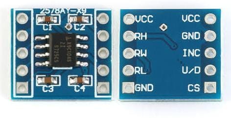
Does X9C104 digital potentiometer can replace machanical 100k ohm potentiometer, which regulate 100 voltage
I am using ESP32 board for this
And using Blynk for automation part
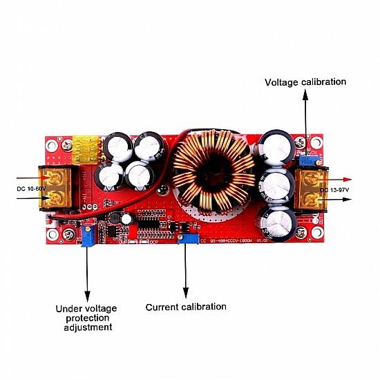
I want to use this digital potentiometer to control Below link DC to DC boost converter
https://www.electronicscomp.com/1200w-dc-dc-boost-step-up-converter-8-60v-to-12-83v-20a?gclid=EAIaIQobChMI3OHdrpyJ_wIVk3BgCh1V4A9JEAQYASABEgLbzPD_BwE
Which have 3 potentiometer
2nos to control voltage and 1no to control current
I tried it last week and I burned it.
I used it to control a DC power supply with 0 to 220v DC output. (LY-820)
The X9C104 is rated at 10mw and those multi-turn trim pots are normally rated at about 500mw, so not difficult to overload them.
Pete.
Can we use Resister or capacitor to control voltage or current, to get it work
Can you try to find out as per your requirement how much capacity resister require to give it safe voltage, and try once again after that
I’m guessing you don’t know much about electronic circuit design?
Pete.
1 Like
Yes You are right,
Can you tell me right way to do this.
I found this video explaining to use resistor to protect Module
What EXACTLY are you trying to achieve, what is the purpose of your project?
Pete.
My Purpose is to operate machanical potentiometer (which is on DC to DC boost converter) from mobile blynk app
I want this for my universal solar charger project
Sounds like you need to look at PWM charger circuits.
Pete.
1 Like
Maybe you can try a stepper motor attached to the physical potentiometer? or you can drive the IGBT MOSFET with Arduino PWM ?
1 Like
Stepper motor would be last option if anything did not work, but i think there must be some other way
Unless you share much more detail about EXACTLY what it is that your project is about, what you are trying to achieve, and where Blynk fits in to the equation then I’m not going to comment further.
Pete.
1 Like
I found this video which I think give a clue to control module from burning
This resistor and capacitor technic works on voltage sensor
Below is link for your reference, if you desided to give a change again to your experiment
I think I had given details above which I have pete,
About device, module and my project.
And I think PWM is the right way which you suggested.
But need to know how it’s work with hardware and software also
Well, it’s not enough information for me, so I’ll step back and leave you to come-up with a solution that works for you.
Good luck with your project.
Pete.
1 Like