At the beginning everything was OK with my first made button on Blynk app (iphone).
But then I added some code for BMP180 and DHT11 sensors + 2 Gauge, 1 Value Display, 1 Labeled Value widgets for temperature, humidity and pressure readings.
Then I connected back the relay and noticed that digital pin is turned HIGH with no reason (from app side).
I changed the digital pin to another. At first it was LOW, but when i make a new button setting in Blynk app and press to play the new button widget, then the digital pin turns HIGH and i cant turn it OFF with the Blynk button.
Maybe something wrong or not enough in the code - no idea, I’m beginner.
Plz help. Excited about this app.
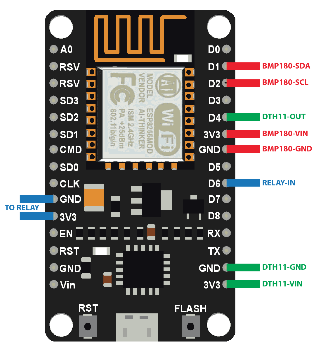
BMP180 - D1, D2
DHT11 - D4
Relay V5 (with seperate power, ground together with Nodemcu G) - D3 (the same problem with D5, D6, D7 pin’s)
All sensor readings works fine.
Problems with the relay only.
#define BLYNK_PRINT Serial
#include <SPI.h>
#include <DHT.h>
#include <ESP8266WiFi.h>
#include <BlynkSimpleEsp8266.h>
#include <SimpleTimer.h>
#include <Wire.h>
#include <Adafruit_BMP085.h>

char auth[] = "xxxxxxx";

char ssid[] = "xxx";
char pass[] = "xxx";

#define DHTPIN 2

#define DHTTYPE DHT11

DHT dht(DHTPIN, DHTTYPE);
SimpleTimer timer;
Adafruit_BMP085 bmp;

void sendSensor()
{
  float h = dht.readHumidity();
  float t = dht.readTemperature();
  float c = bmp.readTemperature();
  float p = bmp.readPressure();

  if (isnan(h) || isnan(t)) {
    Serial.println("Failed to read from DHT sensor!");
    return;
  }

  Blynk.virtualWrite(V5, h);  //V5 is for Humidity
  Blynk.virtualWrite(V6, t);  //V6 is for Temperature
  Blynk.virtualWrite(V7, c); //bmp180
  Blynk.virtualWrite(V8, (bmp.readPressure() / 133.3F));
}

void setup()
{

  Serial.begin(115200);
  Blynk.begin(auth, ssid, pass);

  dht.begin();
  bmp.begin();

  timer.setInterval(1000L, sendSensor);
}

void loop()
{
  Blynk.run();
  timer.run();
}
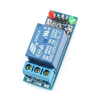
Relay V5 (with seperate power, ground together with Nodemcu G)
VCC - seperate 5V DC
GND - connected together with 5V DC GND and G of NodeMcu
IN - D3 (the same problem with D5, D6, D7 pin’s)
Okay, first of all, pin D3 (GPIO 0) isn’t a good choice of pin for your relay. See this article:
Also, you’re not defining any pinmode for the relay pin, or have any code to control it. You may be doing some direct digital pin manipulation from a widget in the app, but you don’t mention this.
You don’t say if your relay is active HIGH or active LOW, but a pinmode statement in your void setup, followed by a digitalwrite command to set the pin to the opposite of what your relay needs to activate, should do the trick.
From this turns out that:
ESO8266
Good pins for Relays: D1, D2, D6, D8
Good pins for Sensors: D1, D2, then D5, D6, D7
I changed my pin for relay to D6 (GPIO12) and also the VCC and GND of relay to NodeMcu board (before was external 5v).
And now my relay works, although it is active at the start
Yes, I make the pinmode statements in Blynk widget settings.
You’re probably better sticking with the external PSU and shared Ground, as you’ll probably get better stability.
You can manipulate the values of digital pins n the widgets, but setting the pinmode is done in code on the NodeMCU. It’s not necessary to set the pinmode inless you’re changing the values of the pins within the code, but as I said, a pin,ode declaration followed by a digitalwrite command to put your relay to the state you want at boot-up is one way to go. I’d probably follow that with a blink.sync command to then synchronise the relay with the state of the switch in the app.
Looks, like I have to put some pinmode in the code.
Because if i set LOW in Blynk app, anyway relay starts as HIGH.
Then i switch button ON (nothing happens), then OFF and relay goes LOW(OFF).
Yes pin declarations are almost always needed, but you should also look into Virtual Pins and how to properly use them. Direct pin manipulation works, kinda, but has a lot of limitations.
I don’t think a sync will work in this case due to the fact that his switch in the APP is tied directly to the digital pin, and not a virtual one. Although I may be wrong about this.
I did put some code in (int reley and pinmode&digitalwrite in setup)
But it didn’t work. when i switch the NodeMcu on, the relay immediately turns HIGH.
If i take the power from Nodemcu 3v, then i can turn the relay off from app.
Off course first i press ON (in the Blynk app) and nothing heppens, and then if I press OFF, then relay turns LOW.
But if I take some external 5v power for the relay, then it turns HIGH and i can’t turn it OFF from Blynk app.
#include <SPI.h>
#include <DHT.h>
#include <ESP8266WiFi.h>
#include <BlynkSimpleEsp8266.h>
#include <SimpleTimer.h>
#include <Wire.h>
#include <Adafruit_BMP085.h>

const int relejs1 = 12;

char auth[] = "xxxx";

char ssid[] = "xxx";
char pass[] = "xxx";

#define DHTPIN 2
#define DHTTYPE DHT11

DHT dht(DHTPIN, DHTTYPE);
SimpleTimer timer;
Adafruit_BMP085 bmp;

void sendSensor()
{
  float h = dht.readHumidity();
  float t = dht.readTemperature();
  float c = bmp.readTemperature();
  float p = bmp.readPressure();

  if (isnan(h) || isnan(t)) {
    Serial.println("Failed to read from DHT sensor!");
    return;
  }

  Blynk.virtualWrite(V5, h);  //V5 is for Humidity
  Blynk.virtualWrite(V6, t);  //V6 is for Temperature
  Blynk.virtualWrite(V7, c); //bmp180
  Blynk.virtualWrite(V8, (bmp.readPressure() / 133.3F));
}

void setup()
{
  pinMode(relejs1, OUTPUT);
  digitalWrite(relejs1, LOW);
  Serial.begin(9600);
  Blynk.begin(auth, ssid, pass);

  dht.begin();
  bmp.begin();

  timer.setInterval(1000L, sendSensor);
}

void loop()
{
  Blynk.run();
  timer.run();
}```
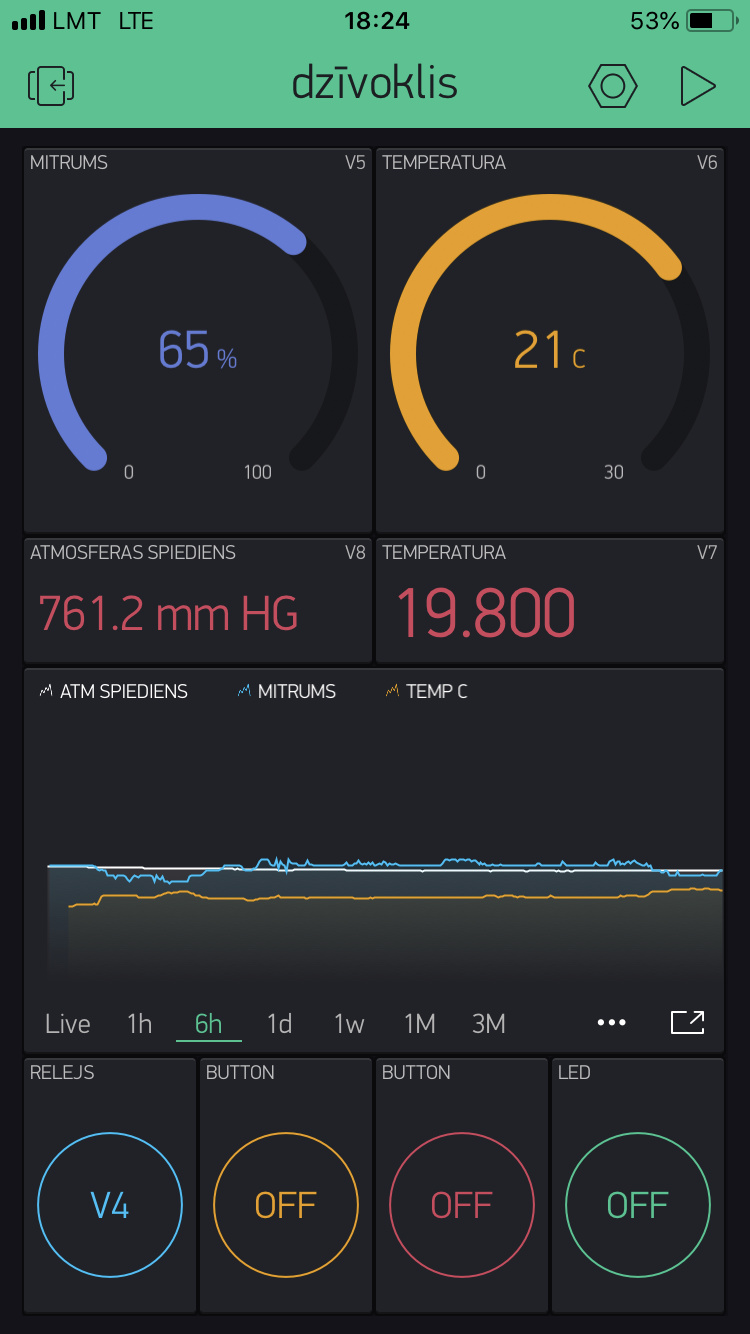
Maybe if you included a screenshot of your app in “stopped” mode, and a description of exactly what you’re trying to achieve, what is working (if anything) and what isn’t; then we might be able to help.
I’m trying to get the relay work together with BMP180 and DTH11 sensors.
The relay worked fine without these sensors and without extra code in sketch (just Blynk app settings and digital pins).
It was working fine also on digital pin, with extra coding in sketch, but only with power from NodeMcu (not with external 5V power).
Would like to get it work with virtual pins.
#define BLYNK_PRINT Serial
#include <SPI.h>
#include <DHT.h>
#include <ESP8266WiFi.h>
#include <BlynkSimpleEsp8266.h>
#include <SimpleTimer.h>
#include <Wire.h>
#include <Adafruit_BMP085.h>

char auth[] = "xxx";
char ssid[] = "xxx";
char pass[] = "xxx";

const int RELAY1 = 12; //D6

#define DHTPIN 2
#define DHTTYPE DHT11
DHT dht(DHTPIN, DHTTYPE);
SimpleTimer timer;
Adafruit_BMP085 bmp;

// Every time we connect to the cloud...
BLYNK_CONNECTED() {
  // Request the latest state from the server
  Blynk.syncVirtual(V4); //make relay state of button upon connection to BLYNK

}

// When App button is pushed - switch the state
BLYNK_WRITE(V4) {
 int relayState = param.asInt();
  if (relayState == 1){
 digitalWrite(RELAY1, LOW);//turn on relay
 }
else if (relayState == 0){
 digitalWrite(RELAY1, HIGH);//turn off relay
  }
}

void sendSensor()
{
  float h = dht.readHumidity();
  float t = dht.readTemperature();
  float c = bmp.readTemperature();
  float p = bmp.readPressure();

  if (isnan(h) || isnan(t)) {
    Serial.println("Failed to read from DHT sensor!");
    return;
  }
  Blynk.virtualWrite(V5, h);  //V5 is for Humidity
  Blynk.virtualWrite(V6, t);  //V6 is for Temperature
  Blynk.virtualWrite(V7, c); //bmp180
  Blynk.virtualWrite(V8, (bmp.readPressure() / 133.3F));
}

void setup()
{
  Serial.begin(9600);
  Blynk.begin(auth, ssid, pass);
  pinMode(RELAY1, OUTPUT);
  digitalWrite(RELAY1, HIGH); //make relay off at startup
  dht.begin();
  bmp.begin();

  timer.setInterval(1000L, sendSensor);
}

void loop()
{
  Blynk.run();
  timer.run();
}
This assumes relay is active LOW, and the button widget outputs a 1 when pressed and a 0 when not-pressed.