D1 Mini occasionally Crashes and reboot when I turn on a virtual switch

Good Day!
I am working on a Remote Start/Stop System for a Generator using a Wemos D1 Mini Pro.
It works great, however occassionally when I press vPin V1 or V9, the board crashes and reboots. I have simplified my code as far as possible and have no idea why it occurs occasitionally.

When I look at the serial monitor, the error decodes to something involving watchdog, I have no idea what that is and read that feeding the watchdog is a fix, but it still happens.

Again this doesnt happen all the time, its just random. This doesnt happen to any of the other vPins such as V10.
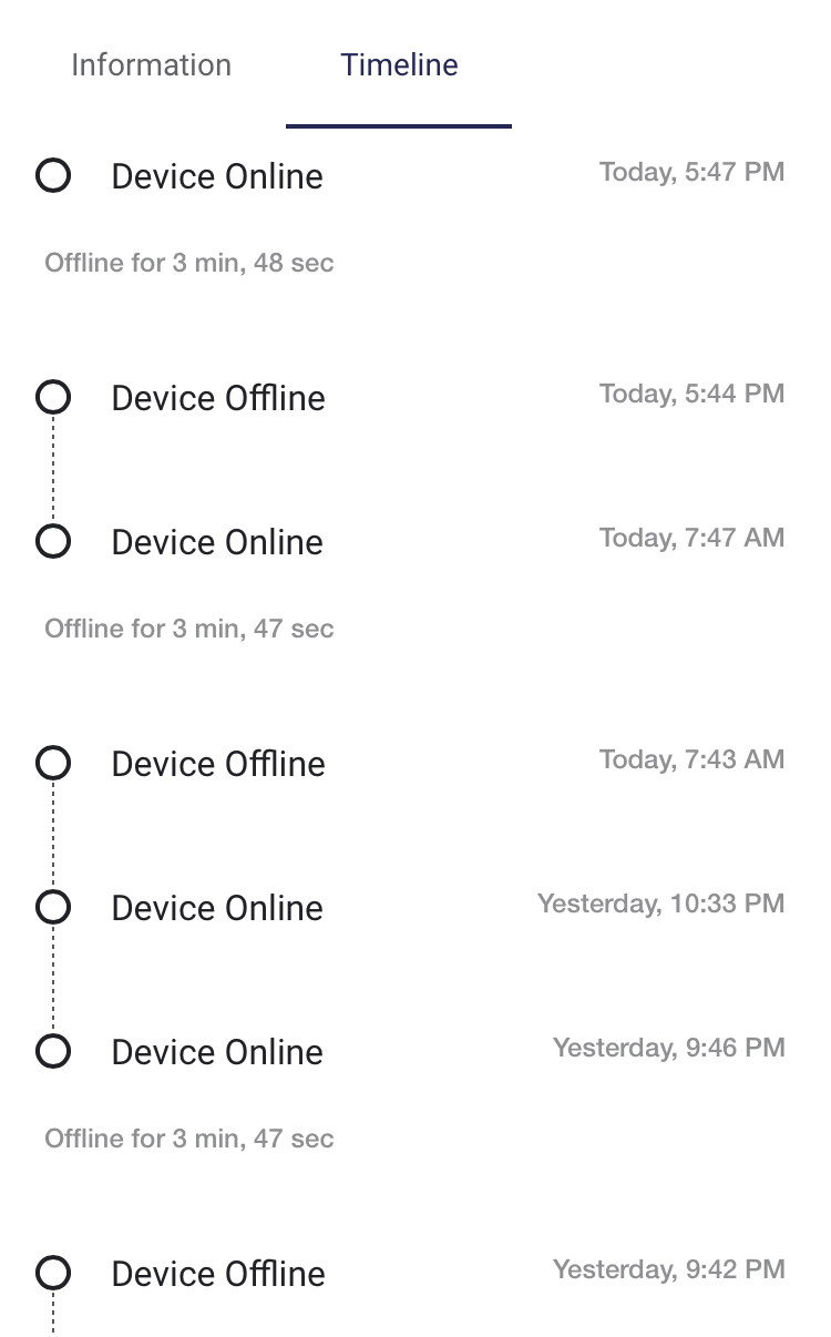
Also when i look at the device timeline, the board goes offline and reconnects at random times when I don’t interact with the app, please see attached screenshot.

I am using the latest blynk library (1.01) and my internet connection is stable.

I would really like to make my project as reliable as possible and I look forward for some advice on how to solve this.
Thanks in advance.


/*
 * Remote Generator Start/Stop System (BLYNK 2.0)
 * Developed By AL
 */

#define BLYNK_TEMPLATE_ID "TMPL_vJdFuLm"
#define BLYNK_DEVICE_NAME "Yamaha EF5500EFW"
#define BLYNK_PRINT Serial
#define BLYNK_FIRMWARE_VERSION        "0.3.1"
#define BLYNK_PRINT Serial
#define APP_DEBUG
#include <SoftwareSerial.h>
#include <RCSwitch.h> 

#define BLYNK_GREEN     "#23C48E"
#define BLYNK_RED       "#D3435C"

#define USE_NODE_MCU_BOARD

#include "BlynkEdgent.h"

RCSwitch mySwitch = RCSwitch(); 

unsigned long previousMillis = 0;
unsigned long interval = 30000;

int CEBsensor = 0; 
int CEBstate = 0;

int Vsensor = A0; // 0-25v voltage sensor is connected with the analog pin A0 of the arduino
//For 0-25v voltage sensor
float correctionfactor = 7.40; 
float vout = 0.0; 
float vin = 0.0; 

// two resistors 30K and 7.5k ohm on Voltage Sensor
float R1 = 30000;  //   
float R2 = 7500; //  
int value = 0; 

BlynkTimer timer;

int newTimer = 1;

String myString; // complete message from arduino, which consistors of snesors data
char rdata; // received charactors

int firstVal, secondVal,thirdVal; // sensors 


void setup()
{
  Serial.begin(115200);
  delay(100);
  BlynkEdgent.begin();
  pinMode(Vsensor, INPUT); //Voltage Sensor
  mySwitch.enableTransmit(D5); //RF Transmitter
  pinMode(D6, OUTPUT);  //UPS Relay
  pinMode(D1, INPUT); //CEB LDR Sensor
  
  timer.setInterval(1000L,sensorvalue1); 
}

void loop() {
   BlynkEdgent.run();
   timer.run(); // Initiates BlynkTimer
   ESP.wdtFeed();
   
   CEBsensor = digitalRead(D1); //LDR Sensor 
   
   //If Coil ON and CEBsensor LOW, Send Alert 
   if(CEBsensor == LOW && CEBstate == HIGH){ 
   WidgetLED led13(V13);
   led13.on(); //Shutoff Indicator ON
   } else {
   WidgetLED led13(V13);
   led13.off(); //Shutoff Indicator OFF
   }

   //CEB Status LED
   if(CEBsensor == HIGH){
   WidgetLED led14(V14);
   led14.on(); //CEB Status (ON) Green
   Blynk.setProperty(V14, "color", "#D3435C");
   } else {
   WidgetLED led14(V14); //CEB Status (OFF) RED
   Blynk.setProperty(V14, "color", "#23C48E");
   }  
   
  ESP.wdtFeed();
}

BLYNK_CONNECTED() {
    Blynk.syncVirtual(V1, V9, V3, V7);
}

void sensorvalue1() 
//Run every second 
{
   int sdata = 0; 
   // read the value at analog input 
   value = analogRead(Vsensor); 
   vout = (value * 5.0) / 1024.0; // see text 
   vin = vout / (R2/(R1+R2));
 
   vin = vin - correctionfactor; 
    
   Blynk.virtualWrite(V5, vin);
   Blynk.virtualWrite(V11, WiFi.localIP().toString());
   Blynk.virtualWrite(V8, map(WiFi.RSSI(), -110, -30, 30, 100));
   Blynk.virtualWrite(V12, CEBsensor);
}

BLYNK_WRITE(V9) 
//attach Button on virtual V9,  
//This will control the Fuel
{ 
    if (param.asInt() == 1){ 
   ESP.wdtFeed();
   mySwitch.send(4617746, 24); //FUEL 
  WidgetLED led2(V7);
  led2.on();
 } 
  if (param.asInt() == 0){ 
   ESP.wdtFeed();
   mySwitch.send(4617746, 24); //FUEL
  WidgetLED led2(V7);
  led2.off();
  }
} 
 
BLYNK_WRITE(V1) 
//attach Button on virtual V1,  
//it will control the Coil 
{ 
    if (param.asInt() == 1){ 
   ESP.wdtFeed();  
   mySwitch.send(4617745, 24); //COIL
  WidgetLED led1(V3);
  led1.on();
  CEBstate = 1;
  } 
   if (param.asInt() == 0){ 
   ESP.wdtFeed();
   mySwitch.send(4617745, 24); //COIL
  WidgetLED led1(V3);
  led1.off();
  CEBstate = 0;
  } 
} 

BLYNK_WRITE(V2) 
//attach Button on virtual V2,  
//it will control the Starter 
{ 
   if(param.asInt()){
    // button pressed for >2Sec
    newTimer = timer.setTimeout(2000,Starter);
  } 
  else {
    timer.disable(newTimer);
  }
}

void Starter() 
{
  Serial.println("System Authorized Start");
  WidgetLED led3(V4);  
  led3.on();
  mySwitch.send(15425809, 24); 
  mySwitch.send(15425809, 24);
  mySwitch.send(15425809, 24);
  led3.off();
}

BLYNK_WRITE(V10) 
//attach Button on virtual V10,  
//it will control the UPS Relay
{ 
    if (param.asInt() == 1){   
   digitalWrite(D6,HIGH); //relay on
  } 
   if (param.asInt() == 0){ 
   digitalWrite(D6,LOW); //relay off
  } 
} 

You should read this
https://docs.blynk.io/en/legacy-platform/legacy-articles/keep-your-void-loop-clean

Thank you for the response.
I will create a new void for the “if” part in the loop. Will update soon

It’s not just a case of moving this stuff out of the void loop, you need to call the new function with a timer rather than every time the void loop executes.

I assume that all of the WDT code has been added to overcome this issue? I’d recommend that you remove it.

Definitions like this, where you define the led2 object as an LED widget:

need to be executed just once, and belong near the top of your - probably near the other code that defines objects such as this:

where the timer object is declared as a Blynk timer.

You’re including the SoftwareSerial library…

but don’t appear to be using it anywhere. Why is it included?

You’re also declaring aliases for the colours #23C48E and #D3435C…

but you’re not using these aliases when you do a Blynk.setProperty for your LED widget objects…

Why?

Pete.

2 Likes
/*
 * Remote Generator Start/Stop System thorugh BLYNK 2.0
 * Developed By AL
 */

#define BLYNK_TEMPLATE_ID "TMPL_vJdFuLm"
#define BLYNK_DEVICE_NAME "Yamaha EF5500EFW"
#define BLYNK_PRINT Serial
#define BLYNK_FIRMWARE_VERSION        "0.3.2"
#define APP_DEBUG
#include <RCSwitch.h> 

#define BLYNK_GREEN     "#23C48E"
#define BLYNK_RED       "#D3435C"

#define USE_NODE_MCU_BOARD

#include "BlynkEdgent.h"

RCSwitch mySwitch = RCSwitch(); 

unsigned long previousMillis = 0;
unsigned long interval = 30000;

int CEBsensor = 0; 
int CEBstate = 0;

int Vsensor = A0; // 0-25v voltage sensor is connected with the analog pin A0 of the arduino
//For 0-25v voltage sensor
float correctionfactor = 7.40; 
float vout = 0.0; 
float vin = 0.0; 

// two resistors 30K and 7.5k ohm on Voltage Sensor
float R1 = 30000;  //   
float R2 = 7500; //  
int value = 0; 

BlynkTimer timer;

WidgetLED led2(V7);
WidgetLED led1(V3);
WidgetLED led14(V14); //CEB Status (OFF) RED
WidgetLED led13(V13);

int newTimer = 1;

String myString; // complete message from arduino, which consistors of snesors data
char rdata; // received charactors

int firstVal, secondVal,thirdVal; // sensors 


void setup()
{
  Serial.begin(115200);
  delay(100);
  BlynkEdgent.begin();
  pinMode(Vsensor, INPUT); //Voltage Sensor
  mySwitch.enableTransmit(D5); //RF Transmitter
  pinMode(D6, OUTPUT);  //UPS Relay
  pinMode(D1, INPUT); //CEB LDR Sensor
  
  timer.setInterval(1000L,sensorvalue1);
  timer.setInterval(1000L,CEBsensor1); 
}

void loop() {
   BlynkEdgent.run();
   timer.run(); // Initiates BlynkTimer
}

BLYNK_CONNECTED() {
    Blynk.syncVirtual(V1, V9, V3, V7);
}

void CEBsensor1() 
//Run every second 
{
  CEBsensor = digitalRead(D1); //LDR Sensor 
   
   //If Coil ON and CEBsensor LOW, Send Alert 
   if(CEBsensor == LOW && CEBstate == HIGH){ 
   led13.on(); //Shutoff Indicator ON
   } else {
   led13.off(); //Shutoff Indicator OFF
   }

   //CEB Status LED
   if(CEBsensor == HIGH){
   led14.on(); //CEB Status (ON) Green
   Blynk.setProperty(V14, "color", "#D3435C");
   } else {
   Blynk.setProperty(V14, "color", "#23C48E");
   }  
}


void sensorvalue1() 
//Run every second 
{
   int sdata = 0; 
   // read the value at analog input 
   value = analogRead(Vsensor); 
   vout = (value * 5.0) / 1024.0; // see text 
   vin = vout / (R2/(R1+R2));
 
   vin = vin - correctionfactor; 
    
   Blynk.virtualWrite(V5, vin);
   Blynk.virtualWrite(V11, WiFi.localIP().toString());
   Blynk.virtualWrite(V8, map(WiFi.RSSI(), -110, -30, 30, 100));
   Blynk.virtualWrite(V12, CEBsensor);
}

BLYNK_WRITE(V9) 
//attach Button on virtual V9,  
//This will control the Fuel
{ 
    if (param.asInt() == 1){ 
   mySwitch.send(4617746, 24); //FUEL 
  led2.on();
 } 
  if (param.asInt() == 0){ 
   mySwitch.send(4617746, 24); //FUEL
  led2.off();
  }
} 
 
BLYNK_WRITE(V1) 
//attach Button on virtual V1,  
//it will control the Coil 
{ 
    if (param.asInt() == 1){ 
   mySwitch.send(4617745, 24); //COIL
  led1.on();
  CEBstate = 1;
  } 
   if (param.asInt() == 0){ 
   mySwitch.send(4617745, 24); //COIL
  led1.off();
  CEBstate = 0;
  } 
} 

BLYNK_WRITE(V2) 
//attach Button on virtual V2,  
//it will control the Starter 
{ 
   if(param.asInt()){
    // button pressed for >2Sec
    newTimer = timer.setTimeout(2000,Starter);
  } 
  else {
    timer.disable(newTimer);
  }
}

void Starter() 
{
  Serial.println("System Authorized Start");
  WidgetLED led3(V4);  
  led3.on();
  mySwitch.send(15425809, 24); 
  mySwitch.send(15425809, 24);
  mySwitch.send(15425809, 24);
  led3.off();
}

BLYNK_WRITE(V10) 
//attach Button on virtual V10,  
//it will control the UPS Relay
{ 
    if (param.asInt() == 1){   
   digitalWrite(D6,HIGH); //relay on
  } 
   if (param.asInt() == 0){ 
   digitalWrite(D6,LOW); //relay off
  } 
} 

I uploaded the above sketch via Blynk Air. Cleaned up the void loop, moved the “WidgetLED” to the top, removed “ESP.wdtFeed();” and “#include <SoftwareSerial.h>”.

As for the “Blynk.setProperty(V14, “color”, “#D3435C”);” , the LED widget vPin 14, changes colour based on the Grid avalability.

However the problem still remains :confused:

No, you didn’t move them, you copied them…

You are also defining an LED widget object here…

You also have random pieces of unused code like this:

as well as the colour aliases that I mentioned earlier.

This level of clutter makes it difficult to easily un-pick the code.

I’m guessing that the native baud rate for your board is 74880, if you used this instead of 115200 …

then you might see more useable info in your serial monitor.
Exactly what is it that you see when the problem occurs, and exactly what triggers the problem?

Pete.

Sorry about the widgetLED, I realized it after posting my previous reply. I will change the baud rate to 74880 and reply back with the errors.

/*
 * Remote Generator Start/Stop System thorugh BLYNK 2.0
 * Developed By AL
 */

#define BLYNK_TEMPLATE_ID "TMPL_vJdFuLm"
#define BLYNK_DEVICE_NAME "Yamaha EF5500EFW"
#define BLYNK_PRINT Serial
#define BLYNK_FIRMWARE_VERSION        "0.3.2"
#define APP_DEBUG
#include <RCSwitch.h> 

#define BLYNK_GREEN     "#23C48E"
#define BLYNK_RED       "#D3435C"

#define USE_NODE_MCU_BOARD

#include "BlynkEdgent.h"

RCSwitch mySwitch = RCSwitch(); 

int CEBsensor = 0; 
int CEBstate = 0;

int Vsensor = A0; // 0-25v voltage sensor is connected with the analog pin A0 of the arduino
//For 0-25v voltage sensor
float correctionfactor = 7.40; 
float vout = 0.0; 
float vin = 0.0; 

// two resistors 30K and 7.5k ohm on Voltage Sensor
float R1 = 30000;  //   
float R2 = 7500; //  
int value = 0; 

BlynkTimer timer;

WidgetLED led1(V3); //COIL LED
WidgetLED led2(V7); //FUEL LED
WidgetLED led3(V4); //STARTER LED
WidgetLED led14(V14); //CEB Status (OFF) RED
WidgetLED led13(V13); //Shutoff LED 

int newTimer = 1;

String myString; // complete message from arduino, which consistors of snesors data
char rdata; // received charactors

int firstVal, secondVal,thirdVal; // sensors 


void setup()
{
  Serial.begin(115200);
  delay(100);
  BlynkEdgent.begin();
  pinMode(Vsensor, INPUT); //Voltage Sensor
  mySwitch.enableTransmit(D5); //RF Transmitter
  pinMode(D6, OUTPUT);  //UPS Relay
  pinMode(D1, INPUT); //CEB LDR Sensor
  
  timer.setInterval(1000L,sensorvalue1);
  timer.setInterval(1000L,CEBsensor1); 
}

void loop() {
   BlynkEdgent.run();
   timer.run(); // Initiates BlynkTimer
}

BLYNK_CONNECTED() {
    Blynk.syncVirtual(V1, V9, V3, V7);
}

void CEBsensor1() 
//Run every second 
{
  CEBsensor = digitalRead(D1); //LDR Sensor 
   
   //If Coil ON and CEBsensor LOW, Send Alert 
   if(CEBsensor == LOW && CEBstate == HIGH){ 
   led13.on(); //Shutoff Indicator ON
   } else {
   led13.off(); //Shutoff Indicator OFF
   }

   //CEB Status LED
   if(CEBsensor == HIGH){
   led14.on(); //CEB Status (ON) Green
   Blynk.setProperty(V14, "color", "#D3435C");
   } else {
   Blynk.setProperty(V14, "color", "#23C48E");
   }  
}


void sensorvalue1() 
//Run every second 
{
   int sdata = 0; 
   // read the value at analog input 
   value = analogRead(Vsensor); 
   vout = (value * 5.0) / 1024.0; // see text 
   vin = vout / (R2/(R1+R2));
 
   vin = vin - correctionfactor; 
    
   Blynk.virtualWrite(V5, vin);
   Blynk.virtualWrite(V11, WiFi.localIP().toString());
   Blynk.virtualWrite(V8, map(WiFi.RSSI(), -110, -30, 30, 100));
   Blynk.virtualWrite(V12, CEBsensor);
}

BLYNK_WRITE(V9) 
//attach Button on virtual V9,  
//This will control the Fuel
{ 
    if (param.asInt() == 1){ 
   mySwitch.send(4617746, 24); //FUEL 
  led2.on();
 } 
  if (param.asInt() == 0){ 
   mySwitch.send(4617746, 24); //FUEL
  led2.off();
  }
} 
 
BLYNK_WRITE(V1) 
//attach Button on virtual V1,  
//it will control the Coil 
{ 
    if (param.asInt() == 1){ 
   mySwitch.send(4617745, 24); //COIL
  led1.on();
  CEBstate = 1;
  } 
   if (param.asInt() == 0){ 
   mySwitch.send(4617745, 24); //COIL
  led1.off();
  CEBstate = 0;
  } 
} 

BLYNK_WRITE(V2) 
//attach Button on virtual V2,  
//it will control the Starter 
{ 
   if(param.asInt()){
    // button pressed for >2Sec
    newTimer = timer.setTimeout(2000,Starter);
  } 
  else {
    timer.disable(newTimer);
  }
}

void Starter() 
{
  Serial.println("System Authorized Start"); 
  led3.on();
  mySwitch.send(15425809, 24); 
  mySwitch.send(15425809, 24);
  mySwitch.send(15425809, 24);
  led3.off();
}

BLYNK_WRITE(V10) 
//attach Button on virtual V10,  
//it will control the UPS Relay
{ 
    if (param.asInt() == 1){   
   digitalWrite(D6,HIGH); //relay on
  } 
   if (param.asInt() == 0){ 
   digitalWrite(D6,LOW); //relay off
  } 
}
ets Jan  8 2013,rst cause:4, boot mode:(3,6)

wdt reset
load 0x4010f000, len 3460, room 16 
tail 4
chksum 0xcc
load 0x3fff20b8, len 40, room 4 
tail 4
chksum 0xc9
csum 0xc9
v00073170
~ld

*Decoding stack results* 0x4010053d: **millis()** at /Users/BSC/Library/Arduino15/packages/esp8266/hardware/esp8266/3.0.2/cores/esp8266/**core_esp8266_wiring.cpp** line **193** 0x402122b1: **__esp_yield()** at /Users/BSC/Library/Arduino15/packages/esp8266/hardware/esp8266/3.0.2/cores/esp8266/**core_esp8266_main.cpp** line **120** 0x4020b578: **ClientContext::wait_until_acked(int)** at /Users/BSC/Library/Arduino15/packages/esp8266/hardware/esp8266/3.0.2/libraries/ESP8266WiFi/src/include/**ClientContext.h** line **347** 0x4020bad5: **WiFiClient::flush(unsigned int)** at /Users/BSC/Library/Arduino15/packages/esp8266/hardware/esp8266/3.0.2/libraries/ESP8266WiFi/src/**WiFiClient.cpp** line **311** 0x4020d1a6: **BearSSL::WiFiClientSecureCtx::flush(unsigned int)** at /Users/BSC/Library/Arduino15/packages/esp8266/hardware/esp8266/3.0.2/libraries/ESP8266WiFi/src/**WiFiClientSecureBearSSL.cpp** line **211** 0x4020d1c0: **BearSSL::WiFiClientSecureCtx::flush()** at /Users/BSC/Library/Arduino15/packages/esp8266/hardware/esp8266/3.0.2/libraries/ESP8266WiFi/src/**WiFiClientSecureBearSSL.h** line **58** 0x4020d0f4: **BearSSL::WiFiClientSecureCtx::_write(unsigned char const*, unsigned int, bool)** at /Users/BSC/Library/Arduino15/packages/esp8266/hardware/esp8266/3.0.2/libraries/ESP8266WiFi/src/**WiFiClientSecureBearSSL.cpp** line **317** 0x4020d013: **BearSSL::WiFiClientSecureCtx::available()** at /Users/BSC/Library/Arduino15/packages/esp8266/hardware/esp8266/3.0.2/libraries/ESP8266WiFi/src/**WiFiClientSecureBearSSL.cpp** line **407** 0x40100428: **ets_post(uint8, ETSSignal, ETSParam)** at /Users/BSC/Library/Arduino15/packages/esp8266/hardware/esp8266/3.0.2/cores/esp8266/**core_esp8266_main.cpp** line **181** 0x4020d138: **BearSSL::WiFiClientSecureCtx::write(unsigned char const*, unsigned int)** at /Users/BSC/Library/Arduino15/packages/esp8266/hardware/esp8266/3.0.2/libraries/ESP8266WiFi/src/**WiFiClientSecureBearSSL.cpp** line **329** 0x40214a0e: **BearSSL::WiFiClientSecure::write(unsigned char const*, unsigned int)** at /Users/BSC/Library/Arduino15/packages/esp8266/tools/xtensa-lx106-elf-gcc/3.0.4-gcc10.3-1757bed/xtensa-lx106-elf/include/c++/10.3.0/bits/**shared_ptr_base.h** line **1324** 0x40203782: **BlynkProtocol >::sendCmd(unsigned char, unsigned short, void const*, unsigned int, void const*, unsigned int)** at /Users/BSC/Documents/Arduino/libraries/blynk-library-master/src/Adapters/**BlynkArduinoClient.h** line **107** 0x402036b4: **BlynkProtocol >::sendCmd(unsigned char, unsigned short, void const*, unsigned int, void const*, unsigned int)** at /Users/BSC/Documents/Arduino/libraries/blynk-library-master/src/Blynk/**BlynkProtocol.h** line **458** 0x40203efc: **BlynkApi > >::setProperty(int, char const (&) [6], char const*)** at /Users/BSC/Documents/Arduino/libraries/blynk-library-master/src/Blynk/**BlynkParam.h** line **104** 0x4021f046: **ethernet_output** at netif/**ethernet.c** line **312** 0x40224dec: **etharp_output_to_arp_index** at core/ipv4/**etharp.c** line **769** 0x40100428: **ets_post(uint8, ETSSignal, ETSParam)** at /Users/BSC/Library/Arduino15/packages/esp8266/hardware/esp8266/3.0.2/cores/esp8266/**core_esp8266_main.cpp** line **181** 0x40100428: **ets_post(uint8, ETSSignal, ETSParam)** at /Users/BSC/Library/Arduino15/packages/esp8266/hardware/esp8266/3.0.2/cores/esp8266/**core_esp8266_main.cpp** line **181** 0x40100428: **ets_post(uint8, ETSSignal, ETSParam)** at /Users/BSC/Library/Arduino15/packages/esp8266/hardware/esp8266/3.0.2/cores/esp8266/**core_esp8266_main.cpp** line **181** 0x40100428: **ets_post(uint8, ETSSignal, ETSParam)** at /Users/BSC/Library/Arduino15/packages/esp8266/hardware/esp8266/3.0.2/cores/esp8266/**core_esp8266_main.cpp** line **181** 0x40100428: **ets_post(uint8, ETSSignal, ETSParam)** at /Users/BSC/Library/Arduino15/packages/esp8266/hardware/esp8266/3.0.2/cores/esp8266/**core_esp8266_main.cpp** line **181** 0x40100428: **ets_post(uint8, ETSSignal, ETSParam)** at /Users/BSC/Library/Arduino15/packages/esp8266/hardware/esp8266/3.0.2/cores/esp8266/**core_esp8266_main.cpp** line **181** 0x40100428: **ets_post(uint8, ETSSignal, ETSParam)** at /Users/BSC/Library/Arduino15/packages/esp8266/hardware/esp8266/3.0.2/cores/esp8266/**core_esp8266_main.cpp** line **181** 0x40100428: **ets_post(uint8, ETSSignal, ETSParam)** at /Users/BSC/Library/Arduino15/packages/esp8266/hardware/esp8266/3.0.2/cores/esp8266/**core_esp8266_main.cpp** line **181** 0x40100428: **ets_post(uint8, ETSSignal, ETSParam)** at /Users/BSC/Library/Arduino15/packages/esp8266/hardware/esp8266/3.0.2/cores/esp8266/**core_esp8266_main.cpp** line **181** 0x40100522: **millis()** at /Users/BSC/Library/Arduino15/packages/esp8266/hardware/esp8266/3.0.2/cores/esp8266/**core_esp8266_wiring.cpp** line **193** 0x40211299: **String::concat(char const*, unsigned int)** at /Users/BSC/Library/Arduino15/packages/esp8266/hardware/esp8266/3.0.2/cores/esp8266/**WString.cpp** line **309** 0x4020110c: **S2Stream::write(unsigned char const*, unsigned int)** at /Users/BSC/Library/Arduino15/packages/esp8266/hardware/esp8266/3.0.2/cores/esp8266/**StreamString.h** line **109** 0x4020111d: **S2Stream::write(unsigned char const*, unsigned int)** at /Users/BSC/Library/Arduino15/packages/esp8266/hardware/esp8266/3.0.2/cores/esp8266/**StreamString.h** line **109** 0x4020110c: **S2Stream::write(unsigned char const*, unsigned int)** at /Users/BSC/Library/Arduino15/packages/esp8266/hardware/esp8266/3.0.2/cores/esp8266/**StreamString.h** line **109** 0x40100ebc: **malloc(size_t)** at /Users/BSC/Library/Arduino15/packages/esp8266/hardware/esp8266/3.0.2/cores/esp8266/umm_malloc/**umm_malloc.cpp** line **821** 0x40100ef4: **realloc(void*, size_t)** at /Users/BSC/Library/Arduino15/packages/esp8266/hardware/esp8266/3.0.2/cores/esp8266/umm_malloc/**umm_malloc.cpp** line **853** 0x40210ed9: **String::changeBuffer(unsigned int)** at /Users/BSC/Library/Arduino15/packages/esp8266/hardware/esp8266/3.0.2/cores/esp8266/**WString.cpp** line **202** 0x40100cb3: **umm_free_core(umm_heap_context_t*, void*)** at /Users/BSC/Library/Arduino15/packages/esp8266/hardware/esp8266/3.0.2/cores/esp8266/umm_malloc/**umm_malloc.cpp** line **549** 0x40100e92: **free(void*)** at /Users/BSC/Library/Arduino15/packages/esp8266/hardware/esp8266/3.0.2/cores/esp8266/umm_malloc/**umm_malloc.cpp** line **595** 0x40210e09: **String::invalidate()** at /Users/BSC/Library/Arduino15/packages/esp8266/hardware/esp8266/3.0.2/cores/esp8266/**WString.h** line **295** 0x4020ee18: **IPAddress::toString() const** at /Users/BSC/Library/Arduino15/packages/esp8266/hardware/esp8266/3.0.2/cores/esp8266/**WString.h** line **79** 0x40100e92: **free(void*)** at /Users/BSC/Library/Arduino15/packages/esp8266/hardware/esp8266/3.0.2/cores/esp8266/umm_malloc/**umm_malloc.cpp** line **595** 0x40204741: **CEBsensor1()** at /Users/BSC/Documents/Arduino/Blynk_2.0_Test_FINAL/**Blynk_2.0_Test_FINAL.ino** line **90** 0x402092d8: **BlynkMillis()** at /Users/BSC/Documents/Arduino/libraries/blynk-library-master/src/utility/**BlynkDebug.cpp** line **291** 0x402094e4: **BlynkTimer::run()** at /Users/BSC/Documents/Arduino/libraries/blynk-library-master/src/utility/**BlynkTimer.cpp** line **109** 0x402090d0: **loop()** at /Users/BSC/Documents/Arduino/Blynk_2.0_Test_FINAL/**Blynk_2.0_Test_FINAL.ino** line **68** 0x402123e8: **loop_wrapper()** at /Users/BSC/Library/Arduino15/packages/esp8266/hardware/esp8266/3.0.2/cores/esp8266/**core_esp8266_main.cpp** line **201**

I ran a exception decorder. I have no clue what to make out of it
Also on 74880, the crash seems to be happening more often.

What puzzles me most is this only happens with vPin 1 and 9!

Have you tried commenting the mySwitch.send function out ?
Like this

BLYNK_WRITE(V1) 
//attach Button on virtual V1,  
//it will control the Coil 
{ 
    if (param.asInt() == 1){ 
   //mySwitch.send(4617745, 24); //COIL
  led1.on();
  CEBstate = 1;
  } 
   if (param.asInt() == 0){ 
   //mySwitch.send(4617745, 24); //COIL
  led1.off();
  CEBstate = 0;
  } 
}

I will try that now. However it is essential for my project to work.

Well well, looks like we have found the problem! I can spam the vPin button and the board no longer crashes.
But I can’t celebrate yet as I need “mySwitch.send” run as thats how I am controlling the generator (by cloning the RF remote signal which controls the gen).

I always suspected it might be a power related issue, but the board is being powered by a iPad Charger which is outputing 2.1A via the usb port. Would it make any diiference if I power the board from the 5V pin?

Do you think the RCSwitch.h library is at fault?

Cheers

Does it crash when you move the #include <RCSwitch.h> after the #include “BlynkEdgent.h” ?
Like this

#include "BlynkEdgent.h"

#include <RCSwitch.h>
RCSwitch mySwitch = RCSwitch(); 

Are you using the RC -Swuitch library from here:

and do you have version 2.6.1 installed (your compiler will tell you the version near the end of the compilation process, but you may need to have verbose compiler messages turned on).

Pete.

@PeteKnight I have version 2.6.4 installed from the arduino library manager. That is the latest version available.

@John93 made the changes and unfortunately it still does.

Currently the RF Transmitter is powered by the 5V pin on the board.

Tomorrow I will disconnect the VCC line on the transmitter and see if it still crashes.

If it doesn’t then great. I will simply power it externally with 5V.

However will it still transmit RF signals if it is not powered by the board and only the signal wire is connected to pin D5?

Yes, provided it that they share a common ground.

Personally, I doubt if it’s a power issue. I use D1 Mini’s powered via the USB socket to transmit 433MHZ signals using a typical transmit module that is powered from the Wemos.

Pete.

1 Like

Update:

I changed the way I am powering the board. It is now powered by a 12V battery from the UPS using a buck converter to 5V. This was a change I was wanting to make as the board will have uninterrupted, long lasting power supply during power outages.

The RF transmitter is connected to the output 5V on the buck converter and common ground, and signal wire to pin D5.

Good news, the crash is now less frequent, and its a definite improvement. At this stage I belive the code is as good as it gets and hardware will need improvement.

Thank you @PeteKnight and @John93 for the valuble help :slight_smile:

2 Likes

Update:
After a lot of research, I believe I have found the main reason why I was getting occasional reboots.

It turns out my D1 mini is a clone.The seller on eBay claimed that it was genuine.

I read on another forum that clones have an insufficient voltage regulator which pumps out only 150mA peak current. After close inspection of my board, I indeed have the same crappy voltage regulator marked “4B2K”.

This is such a disappointment and I wish I checked this first before spending days on looking for errors in the code.

At this point, I will attempt to replace the voltage regulator with a “DE-A1D” which on paper has similar parameters but has a max output current of 300mA.

Hopefully this will fix it🤞🏻

I use Wemos D1 Mini’s extensively, and the majority - if not all - of mine are clones.

I’ve never had an issue with the voltage regulator causing disconnections.

Pete.

Strange. May I know what voltage regulator is fitted on your boards?