Hello Everyone,
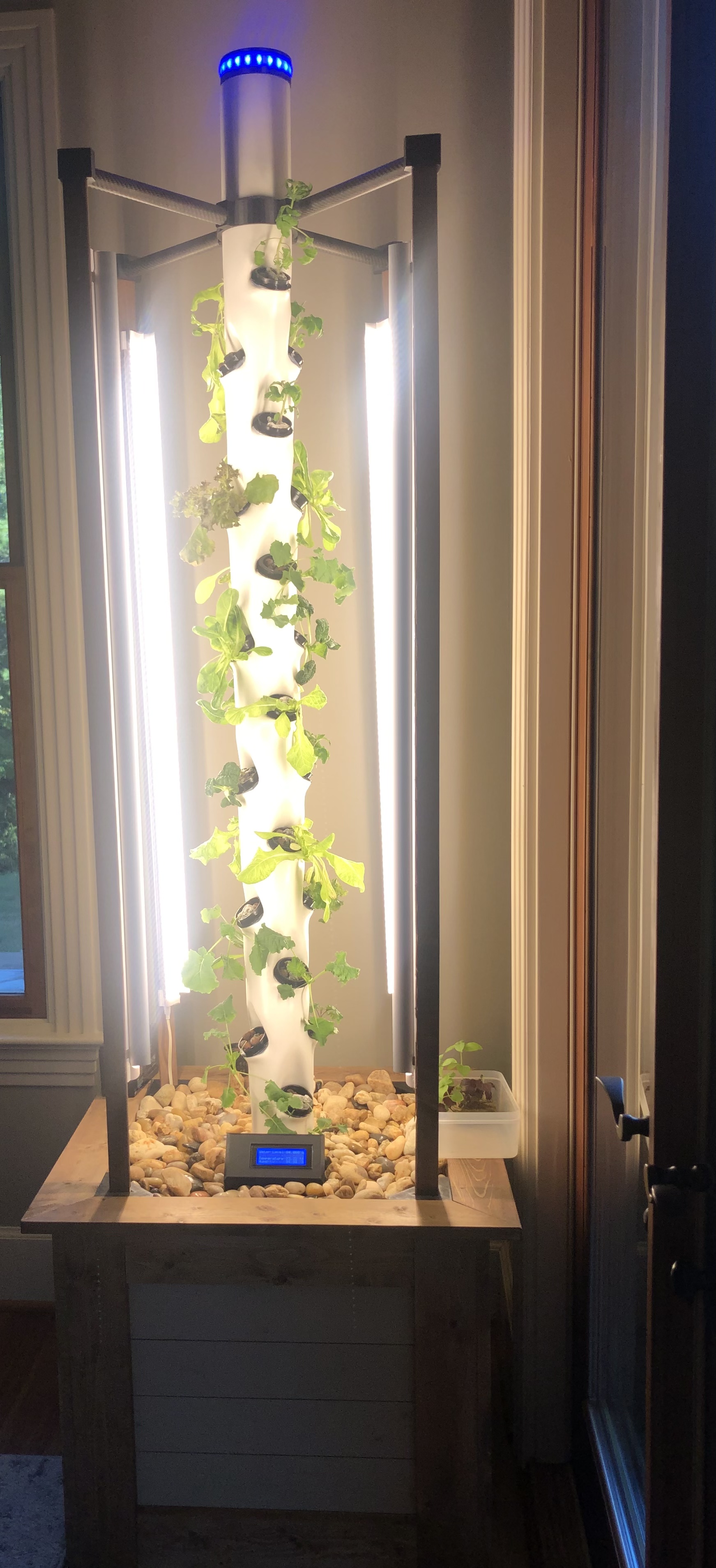
Currently I am working on a Hydroponic Tower where I am monitoring several sets of data. Additionally I have alarms set which turn on the lights and water pump at defined intervals as per the code below. The system itself, overall, works as I need it. I’m still making some fine adjustments as I go along. At the moment, all the data going to the Blynk app(version 3.4.5) and I am able to view the data in realtime via an Arduino Uno Rev. 2 wifi.
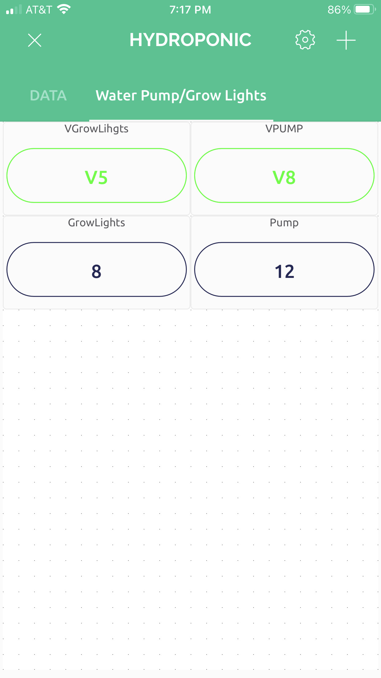
Where I am running into an issue is controlling and monitoring both the Pump and Lights. These are connected to their respective relay where their data pins are connected and controlled by the Uno. As a note, there are no physical buttons within the system.
Current Issue with Virtual Buttons:
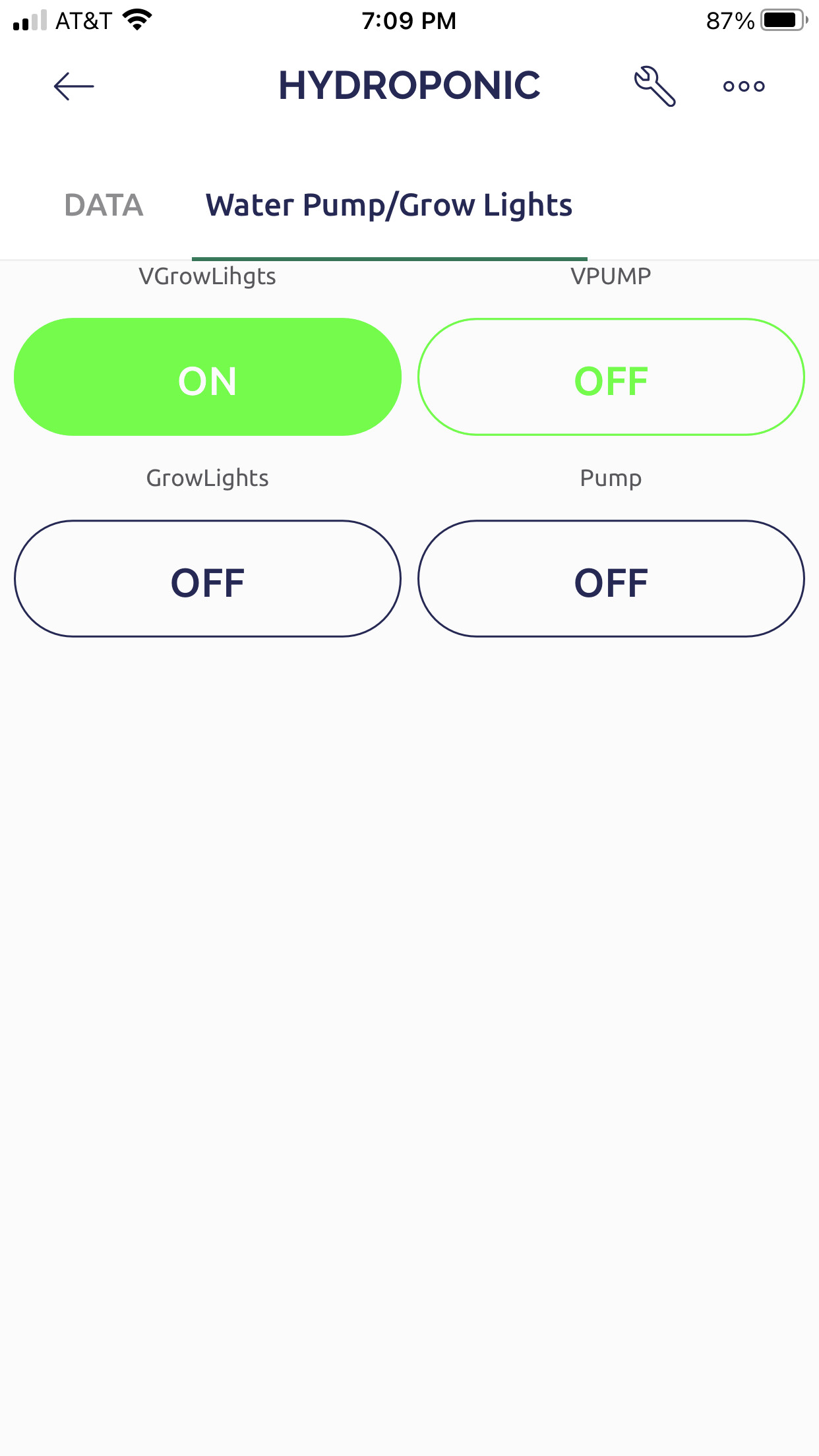
Virtual Button1
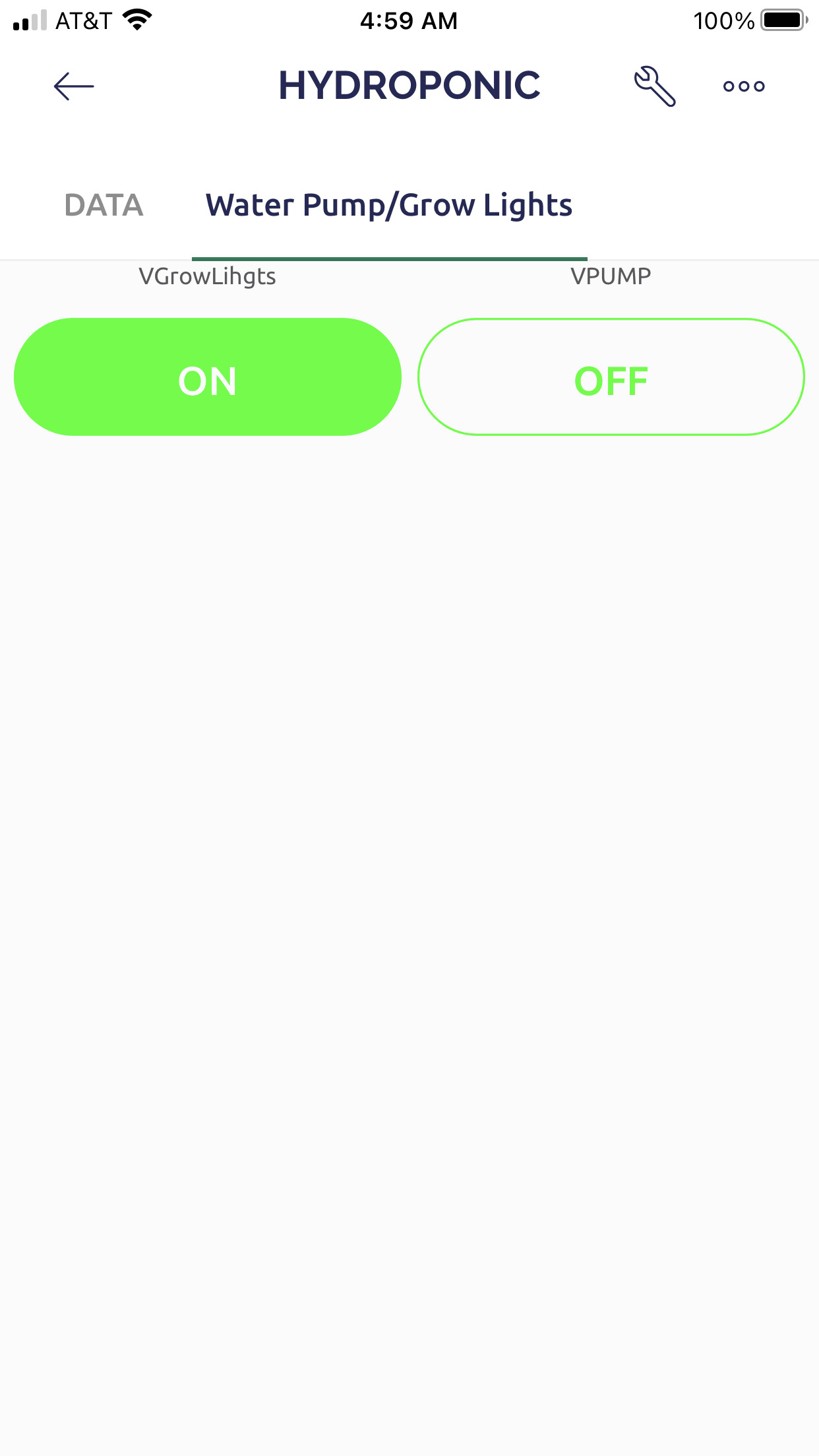
- Initially after code is uploaded. Button is Highlighted “ON” and light turns on. When toggled
to turn off, the lights turn off and button show “Off” briefly and then goes back to “On” without
being toggled. Lights are still off even though the button show “On”
- During toggling, briefly the button goes to “Off” then goes back to “On” Lights still remain off
- Work around was to create a digital button in order to have control of the lights remotely.
However, this does not provide current status when they system running in
automation(defined timings in code).
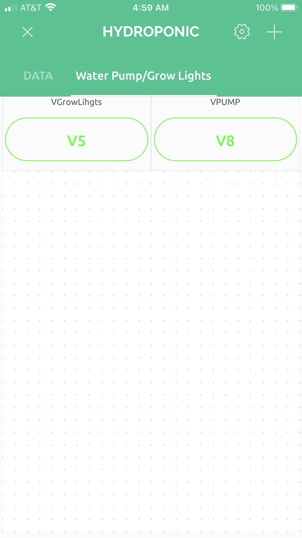
VButton Settings:
- Connected to V5 Datastream
- Mode set to Switch
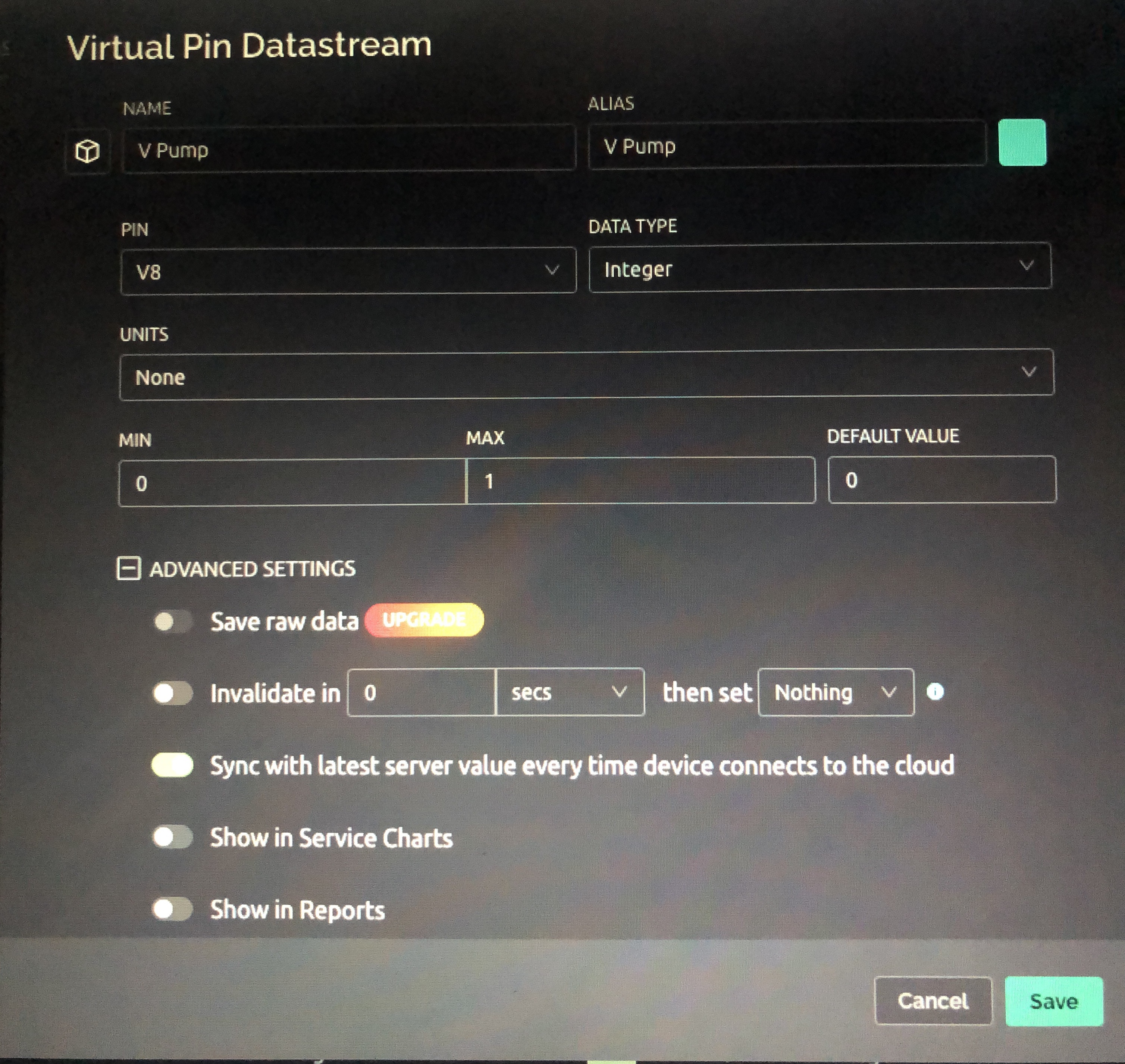
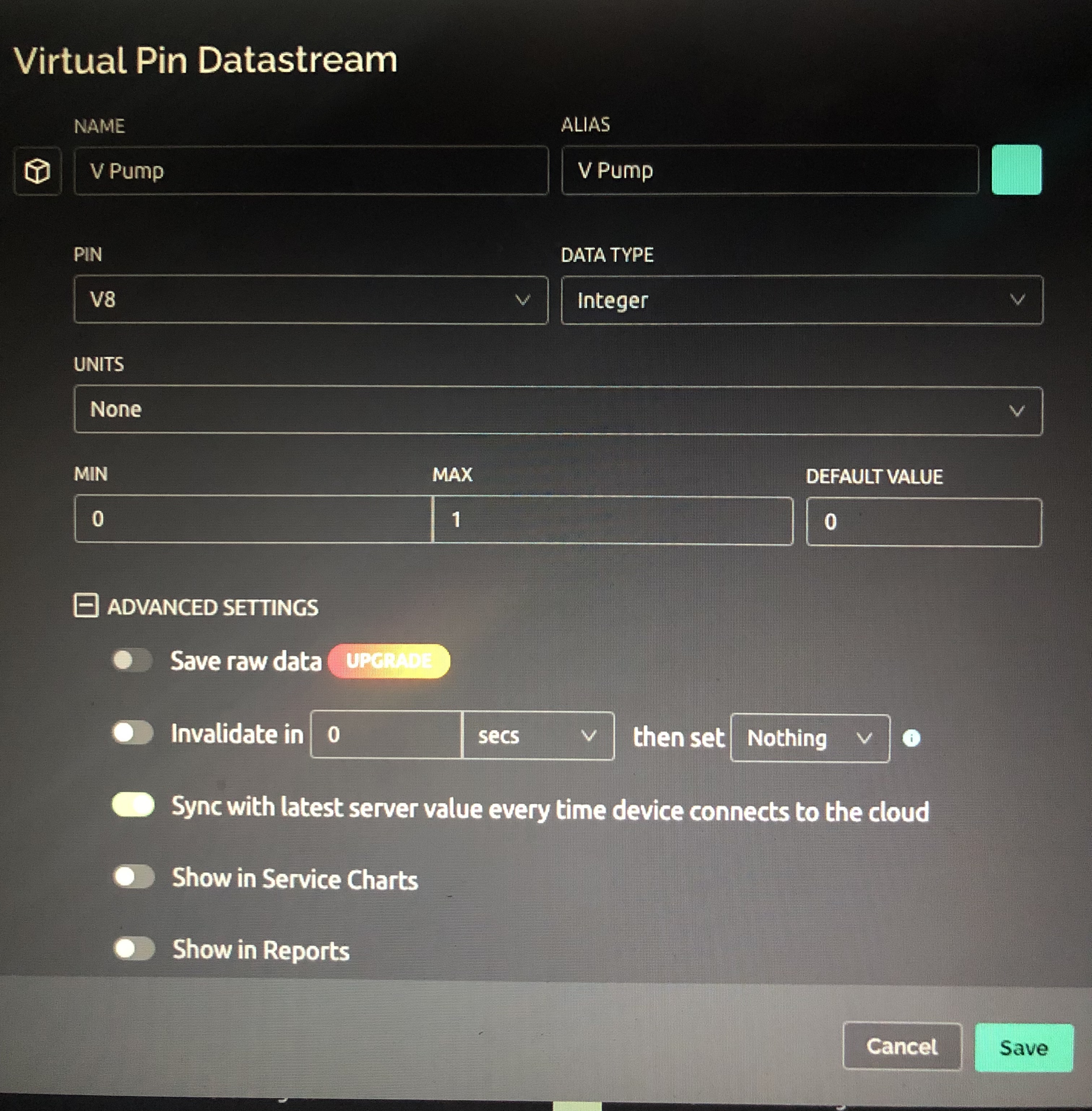
Virtual Button2
- Button turns Pump On and off as needed when toggled.
- When pump turns on during the defined timings within the code(automation), the status on
the Virtual
button is not correct and does not change accordingly
VButton Settings:
- Connected to V8 Datastream
- Mode set to Switch
I’m sure being new to both Arduino and Blynk, I have something coded wrong so I apologize in advance. Any guidance would be appreciated in trying to obtain the goals below.
Goal:
Virtual Button1 in Blynk app
- Manually toggle Light On/Off
- Provide current Off/On status of Lights(maybe Relay State) within the Virtual Button or
Virtual LED
Virtual Button2
- Manually toggle Pump On/Off
- Provide current Off/On status of Pump(maybe Relay State) within the Virtual Button or
Virtual LED
//temphumid Stuff
#include <DHT.h>
#define DHTTYPE DHT22 // DHT 22 (AM2302), AM2321
#define DHTPIN 2
DHT dht(DHTPIN, DHTTYPE);
int chk;
float hum;  //Stores humidity value
float temp; //Stores temperature value

//LED Stuff
#include <Adafruit_NeoPixel.h>
#ifdef __AVR__
#include <avr/power.h> // Required for 16 MHz Adafruit Trinket
#endif
#define LED_PIN    6
#define LED_COUNT 17
Adafruit_NeoPixel strip(LED_COUNT, LED_PIN, NEO_GRB + NEO_KHZ800);

//Liquid level variables //
int rawLiquidReading;
float liquidLevel;
const long lowEtapeValue = 517;
const long highEtapeValue = 781;
const byte liquidLevelPin = A1;

//Pump and light stuff
#include <Time.h>
#include <TimeAlarms.h>
#include <Wire.h>;
#include <DS1307RTC.h>
#include <TimeLib.h> //added from the TimeRTCSet
int Light = 13;
int Pump = 12;
AlarmId id;


//TDS Stuff
#include <EEPROM.h>
#include "GravityTDS.h"
#include <OneWire.h>
#include <DallasTemperature.h>
#define ONE_WIRE_BUS 7
#define TdsSensorPin A0
OneWire oneWire(ONE_WIRE_BUS);
GravityTDS gravityTds;
DallasTemperature sensors(&oneWire);
float tdsValue = 0;


//Blynk_Wifi Stuff
#include <BlynkSimpleWiFiNINA.h>
#define BLYNK_TEMPLATE_ID "*************"
#define BLYNK_DEVICE_NAME "*************"
#define BLYNK_AUTH_TOKEN "*************"
#define BLYNK_PRINT Serial
#include <SPI.h>
#include <WiFiNINA.h>
char ssid[] = "*************";
char pass[] = "*************";
char auth[] = "*************";
BlynkTimer timer;
BLYNK_WRITE(V5) // Executes when the value of virtual pin 5 changes
{
  if(param.asInt() == 1)
  {
    // execute this code if the switch widget is now ON
    digitalWrite(Light,HIGH);  // Set Light HIGH

    Blynk.virtualWrite(V5,1);  // Turn the widget attached to V5 On
  }
  else
  {
    // execute this code if the switch widget is now OFF
    digitalWrite(Light,LOW);  // Set Light LOW

    Blynk.virtualWrite(V5,0);  // Turn the widget attached to V5 Off
  }
}
BLYNK_WRITE(V8) // Executes when the value of virtual pin 8 changes
{
  if(param.asInt() == 1)
  {
    // execute this code if the switch widget is now ON
    digitalWrite(Pump,HIGH);  // Set Pump HIGH

    Blynk.virtualWrite(V8,1);  // Turn the widget attached to V8 On
  }
  else
  {
    // execute this code if the switch widget is now OFF
    digitalWrite(Pump,LOW);  // Set digital Pump LOW

    Blynk.virtualWrite(V8,0);  // Turn the widget attached to V8 Off
  }
}
BLYNK_CONNECTED()
{
  Blynk.syncVirtual(V5);  // will cause BLYNK_WRITE(V5) to be executed
  Blynk.syncVirtual(V8);  // will cause BLYNK_WRITE(V8) to be executed
}


//lcd stuff
#include <LiquidCrystal_I2C.h>
LiquidCrystal_I2C lcd(0x27, 20, 4);

void setup()
{
  Serial.begin(9600);
  sensors.begin();
  while (!Serial);
  pinMode(Light, OUTPUT);
  digitalWrite(Light, LOW);
  pinMode(Pump, OUTPUT);
  digitalWrite(Pump, LOW);
  pinMode(liquidLevelPin, INPUT);

  strip.begin();           // INITIALIZE NeoPixel strip object (REQUIRED)
  strip.show();            // Turn OFF all pixels ASAP
  strip.setBrightness(50); // Set BRIGHTNESS to about 1/5 (max = 255)


  // first run the example from the following path: file, examples, DS1307RTC, to set the time of the RTC, then upload this sketch
  setSyncProvider(RTC.get);   // the function to get the time from the RTC
  if (timeStatus() != timeSet)
    Serial.println("Unable to sync with the RTC");
  else
    Serial.println("RTC has set the system time");

  // create the alarms, to trigger at specific times
  Alarm.alarmRepeat(6, 0, 0, LightsOn); // Lights on 6:00am every day
  Alarm.alarmRepeat(6, 0, 0, PumpOn); // Pump on 6:00am every day
  Alarm.alarmRepeat(6, 5, 0, PumpOff); // Pump runs for 5 min. and then off every day
  Alarm.alarmRepeat(7, 5, 0, PumpOn); // Pump on 7:05am every day
  Alarm.alarmRepeat(7, 10, 0, PumpOff); // Pump runs for 5 min. and then off every day
  Alarm.alarmRepeat(8, 10, 0, PumpOn); // Pump on 8:10am every day
  Alarm.alarmRepeat(8, 15, 0, PumpOff); // Pump runs for 5 min. and then off every day
  Alarm.alarmRepeat(9, 15, 0, PumpOn); // Pump on 9:15am every day
  Alarm.alarmRepeat(9, 20, 0, PumpOff); // Pump runs for 5 min. and then off every day
  Alarm.alarmRepeat(10, 20, 0, PumpOn); // Pump on 10:20am every day
  Alarm.alarmRepeat(10, 25, 0, PumpOff); // Pump runs for 5 min. and then off every day
  Alarm.alarmRepeat(11, 25, 0, PumpOn); // Pump on 11:25am every day
  Alarm.alarmRepeat(11, 30, 0, PumpOff); // Pump runs for 5 min. and then off every day
  Alarm.alarmRepeat(12, 30, 0, PumpOn); // Pump on 12:30pm every day
  Alarm.alarmRepeat(12, 35, 0, PumpOff); // Pump runs for 5 min. and then off every day
  Alarm.alarmRepeat(13, 35, 0, PumpOn); // Pump on 1:35pm every day
  Alarm.alarmRepeat(13, 40, 0, PumpOff); // Pump runs for 5 min. and then off every day
  Alarm.alarmRepeat(14, 40, 0, PumpOn); // Pump on 2:40pm every day
  Alarm.alarmRepeat(14, 45, 0, PumpOff); // Pump runs for 5 min. and then off every day
  Alarm.alarmRepeat(15, 45, 0, PumpOn); // Pump on 3:45pm every day
  Alarm.alarmRepeat(15, 50, 0, PumpOff); // Pump runs for 5 min. and then off every day
  Alarm.alarmRepeat(16, 50, 0, PumpOn); // Pump on 4:50pm every day
  Alarm.alarmRepeat(16, 55, 0, PumpOff); // Pump runs for 5 min. and then off every day
  Alarm.alarmRepeat(17, 55, 0, PumpOn); // Pump on 5:55pm every day
  Alarm.alarmRepeat(18, 00, 0, PumpOff); // Pump runs for 5 min. and then off every day
  Alarm.alarmRepeat(19, 00, 0, LightsOff); // Lights off at 7:00pm every day, remain off until 6:00am
  Alarm.alarmRepeat(19, 00, 0, PumpOn); // Pump on 7:00pm every day
  Alarm.alarmRepeat(19, 05, 0, PumpOff); // Pump runs for 5 min. and then off every day
  Alarm.alarmRepeat(20, 05, 0, PumpOn); // Pump on 8:05pm every day
  Alarm.alarmRepeat(20, 15, 0, PumpOff); // Pump runs for 5 min. and then off unitl 6:00am every day

  lcd.begin(20, 4);
  Serial.println("Connecting to Blynk...");
  Blynk.begin(auth, ssid, pass, "blynk.cloud", 80);


  gravityTds.setPin(TdsSensorPin);
  gravityTds.setAref(5.0);  //reference voltage on ADC, default 5.0V on Arduino UNO
  gravityTds.setAdcRange(1024);  //1024 for 10bit ADC;4096 for 12bit ADC; 256 for 8 bit
  gravityTds.begin();  //initialization

  int waterValue = analogRead(liquidLevel);


  dht.begin();

  //  Setup a function to be called every second
  //timer.setInterval(1000L, sendSensor);

  lcd.init(); //initialize the lcd
  lcd.backlight(); //open the backlight
  lcd.setCursor(0, 0);
  lcd.print("wLevel");
  lcd.setCursor(0, 1);
  lcd.print("Humid");
  lcd.setCursor(0, 2);
  lcd.print("wTemp");
  lcd.setCursor(0, 3);
  lcd.print("aTemp");
  lcd.setCursor(16, 0);
  lcd.print("TDS");

}

void loop()
{

  digitalClockDisplay();
  Alarm.delay(1000); // wait one second between clock display

  Blynk.run();
  timer.run();
  sensors.requestTemperatures();

  gravityTds.setTemperature(sensors.getTempCByIndex(0));  // set the temperature and execute temperature compensation
  gravityTds.update();  //sample and calculate
  tdsValue = gravityTds.getTdsValue();  // then get the value

  hum = dht.readHumidity();
  temp = dht.readTemperature() * 1.8 + 32;
  lcd.setCursor(8, 0); //Water Level
  lcd.print(liquidLevel, 0); //Water Level value displayed on lcd
  lcd.setCursor(12, 0); //Percent symbol location
  lcd.print("%"); //Percentage symblol
  //lcd.setCursor(16, 1); //TDS Level
  //lcd.print(tdsValue, 0); ///tds value displayed on lcd
  lcd.setCursor(16, 2); //ppm location
  lcd.print("PPM"); //Percentage symblol
  lcd.setCursor(8, 3); //aTemp value
  lcd.print(temp, 0); //avtemperaturevvalue displayed on lcd
  lcd.setCursor(11, 3); //Degree Symbol location
  lcd.print((char)223); //Degree Symbol
  lcd.setCursor(12, 3); //Temperature Symbol location
  lcd.print("F"); //Temperature Symbol
  lcd.setCursor(8, 1); //humidity value
  lcd.print(hum, 0); //humidity Level value displayed on lcd
  lcd.setCursor(12, 1); //Humidity Symbol location
  lcd.print("%"); //Humidity Symbol
  lcd.setCursor(8, 2); //Water Temp Location
  lcd.print(sensors.getTempCByIndex(0) * 1.8 + 32, 0); //Water Temp Value
  lcd.setCursor(11, 2); //wDegree Symbol location
  lcd.print((char)223); //wtem Degree Symbol
  lcd.setCursor(12, 2); //wTaemperature Symbol location
  lcd.print("F  "); //wTemperature Symbol


  rawLiquidReading = analogRead(liquidLevelPin);
  Serial.print("Raw Liquid Level: ");
  Serial.print(rawLiquidReading);

  liquidLevel = map(rawLiquidReading, lowEtapeValue, highEtapeValue, 0, 100);
  Serial.print(" / Liquid Remaining: ");
  Serial.print(liquidLevel);
  Serial.println("%.");


  if (liquidLevel  > 20 && liquidLevel < 50) {
    for (int i = 0; i < 20; i++)
      strip.setPixelColor(i, strip.Color(0, 150, 0));
    strip.show();
  }

  else if (liquidLevel >= 50) {
    strip.clear();
    for (int i = 0; i < 20; i++)
      strip.setPixelColor(i, strip.Color(0, 0, 150));
    strip.show();
  }

  else if (liquidLevel <= 20) {
    strip.clear();
    for (int i = 0; i < 20; i++)
      strip.setPixelColor(i, strip.Color(255, 0, 0));
    strip.show();
  }

  Blynk.virtualWrite(V0, liquidLevel); //water level vpin
  Blynk.virtualWrite(V1, tdsValue); //tds vpin
  Blynk.virtualWrite(V5, temp); //aTemp vpin
  Blynk.virtualWrite(V2, hum); //humidity vpin
  Blynk.virtualWrite(V4, sensors.getTempCByIndex(0) * 1.8 + 32); //wtemp vpin
  Blynk.virtualWrite(V10, rawLiquidReading); //humidity vpin

}


// functions to be called when an alarm triggers


void LightsOn() {

  Serial.println("Alarm: - turn lights On");
  digitalWrite(Light, HIGH);
}


void LightsOff() {
  Serial.println("Alarm: - turn lights Off");
  digitalWrite(Light, LOW);
}

void PumpOn() {
  Serial.println("Alarm: - turn lights On");
  digitalWrite(Pump, HIGH);
}

void PumpOff() {
  Serial.println("Alarm: - turn lights Off");
  digitalWrite(Pump, LOW);
}


void digitalClockDisplay() {
  // digital clock display of the time
  Serial.print(hour());
  printDigits(minute());
  printDigits(second());
  Serial.print(" ");
  Serial.print(day());
  Serial.print(" ");
  Serial.print(month());
  Serial.print(" ");
  Serial.print(year());
  Serial.println();
}

void printDigits(int digits) {
  // utility function for digital clock display: prints preceding colon and leading 0
  Serial.print(":");
  if (digits < 10)
    Serial.print('0');
  Serial.print(digits);
}

void colorWipe(uint32_t color, int wait) {
  for (int i = 0; i < strip.numPixels(); i++) { // For each pixel in strip...
    strip.setPixelColor(i, color);         //  Set pixel's color (in RAM)
    strip.show();                          //  Update strip to match
    delay(wait);                           //  Pause for a moment
  }
}