I am working on a home automation project. In that I have managed to control 16 loads. I used every gpio pins of esp32.
Now I want to add main switch. Like if I want to shut off every light with single push button.
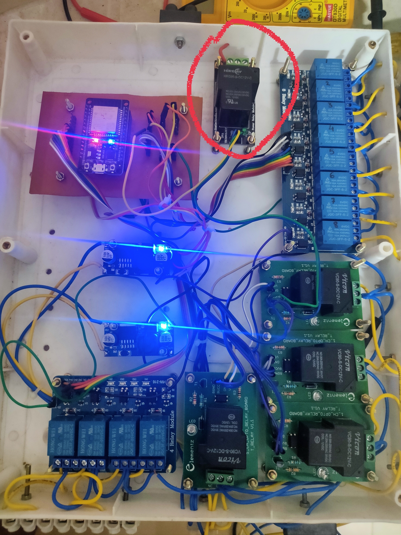
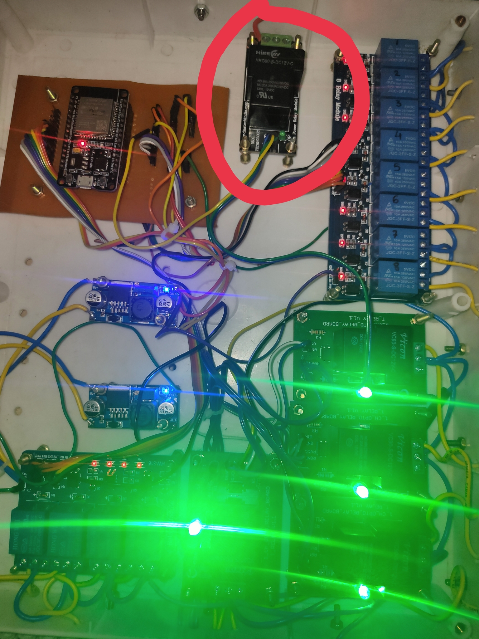
The red circle you see is the T type relay … That is my main switch.
Now here comes the main problem… When I switched off the main switch, loads connected to the different relays switched off but the relays stays ON. Only the supply is being cut off from the load.
Here is the proof
Not that good… I am just good in hardware connections. I read about the virtual pins on blynk but I am kinda confused about it.
My doubt about the virtual pins may sound like a silly or childish but here it is
In the blynk help forum of virtual pins, they said that just connect to digital pin 8 and add the widget D8 and its done. I don’t understand that… In fact I just know about virtual pins theoretically… Or you can say my mind is potato… But I am eager to learn about it.
When a switch widget that is connected to virtual pin 1 is toggled, it causes the function BLYNK_WRITE(V1) to be triggered in your code.
The value of the switch widget (0 for off, 1 for on) can be obtained by using the parm.asInt() command.
You can then use this to change the state of the physical pin(s) that you want to control using a digitalWrite command.
The advantage of this is that you can turn more than one pin on or off using one button widget.
BLYNK_WRITE(V1)
// This function is triggered when the widget attached to V1 changes in the app
{
  int button_v1_value = param.asInt(); // get the value of the button widget and store

  if(button_v1_value == 1)
    {
      // If the button is now On
      digitalWrite(2, LOW);  // set the relay connected to Pin 2 to ON (if active LOW)
      // add more digitalWrites in here if you want to turn more ouns on/off
    }
  else
    {
      // we get here if V1 is Off
      digitalWrite(2, HIGH);  // set the relay connected to Pin 2 to OFF (if active LOW)
      // add more digitalWrites in here if you want to turn more ouns on/off
}
You would also need pinMode declarations for each physical pin used in void setup…
void setup
{
  pinMode(2, OUTPUT); // Physivcal pin 2 will be an output pin
}
Ok now another dumber question… Everyone says when you connect to virtual pins then you write this command… But where is this virtual pin on the board? Or if I connect LED to digital pin 5 and assign as virtual pin 1 and then it controls the LED is it like that?
Thats where I am getting confused… I do understand that code.
(I know I am annoying you)