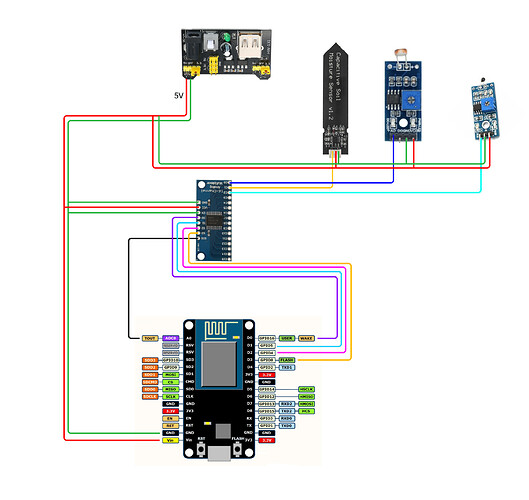
Hi,
I’m having problems with my sketch. I’m receiving the sensor numbers totally scrambled, for example when I shine light to the LDR, the numbers of the other sensors also change.
I’ve already checked the wires and everything seems to be correct.
On beggining I tought it was the timers. I put they on different gaps, but it isn’t working.
Maybe I’m not fully understand how to code for Blynk to read the multiplexer correctly.
Some clue on whats happening?
Sorry my english.
Hardware:
NodeMCU (ESP8266)
Multiplexer 16ch CD74HC4067
Sensors:
LDR Module
Capacitive Soil Moisture Sensor v1.2
Thermistor Module 10K
#define BLYNK_PRINT Serial
#include <ESP8266WiFi.h>
#include <BlynkSimpleEsp8266.h>
#include <Wire.h>
#include <Thermistor.h>

#define S0 D0
#define S1 D1
#define S2 D2
#define S3 D3
#define SIG A0

int sensor0;
int sensor1;
int sensor2;

char auth[] = "xxx";
char ssid[] = "xxx";
char pass[] = "xxx";

BlynkTimer timer;

void setup()
{
  /* Debug console */
  Serial.begin(9600);
  Blynk.begin(auth, ssid, pass);
  Serial.println("");

  /* Timers */
  timer.setInterval(1000L, getSensor0); /* LDR */
  timer.setInterval(2500L, getSensor1); /* Soil */
  timer.setInterval(5000L, getSensor2); /* Thermistor */

  /* Multiplexer */
  pinMode(S0, OUTPUT);
  pinMode(S1, OUTPUT);
  pinMode(S2, OUTPUT);
  pinMode(S3, OUTPUT);
  pinMode(SIG, INPUT);

}

void getSensor0() {
  /* Channel 0 (C0 pin - binary output 0,0,0,0) */
  digitalWrite(S0, LOW); digitalWrite(S1, LOW); digitalWrite(S2, LOW); digitalWrite(S3, LOW);
  sensor0 = analogRead(SIG);

  Blynk.virtualWrite(V0, sensor0);

}

void getSensor1() {
  /* Channel 1 (C1 pin - binary output 1,0,0,0) */
  digitalWrite(S0, HIGH); digitalWrite(S1, LOW); digitalWrite(S2, LOW); digitalWrite(S3, LOW);
  sensor1 = analogRead(SIG);

  Blynk.virtualWrite(V1, sensor1);

}

void getSensor2() {
  /* Channel 2 (C2 pin - binary output 0,1,0,0) */
  digitalWrite(S0, LOW); digitalWrite(S1, HIGH); digitalWrite(S2, LOW); digitalWrite(S3, LOW);
  sensor2 = analogRead(SIG);

  Blynk.virtualWrite(V2, sensor2);

}

void loop()
{
  Blynk.run();
  timer.run();
}
