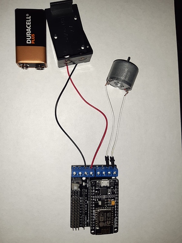
Hi Everyone, My project is, ultimately, to use my voice (Google Assistant) to control my blinds through Blynk. But for now, I am trying to first be able to control a motors speed and direction so I can integrate this into the larger goal of the project. To do this I am using a NodeMCU Motor Shield ESP12E w/ L293D H bridge connected to a 9V battery to power both the motor and the ESP8266 Board.
I’ve read some books and watched tutorials and I’ve written some code in the Arduino IDE. However (you guessed it), I’m running into some issues and can’t see where my problems lie. I would like a button on the Blynk App to ‘Close the blinds’ when off and ‘Open the Blinds’ when on. I haven’t fine-tuned the turning but I just want to see it go in both clockwise and anticlockwise directions when I press the button on the Blynk App.
I would massively appreciate ANY help if it’s spotting where I am going wrong in my code or an article or tutorial that can help me out, Thank You all in advance! Please let me know if I’ve left any details out or if your curious on how I will continue on my project after this is sorted out.
So here’s my code:
#define BLYNK_PRINT Serial

int MotorSpeed = 1;

int MotorDirection = 3;

int speed = 100;

#include <ESP8266WiFi.h>

#include <BlynkSimpleEsp8266.h>

char auth[] = "Auth Key";

char ssid[] = "wifi";

char pass[] = "password";

void setup()

{

  Serial.begin(9600);

  Blynk.begin(auth, ssid, pass);

  pinMode(MotorSpeed, OUTPUT);

  pinMode(MotorDirection, OUTPUT);

  digitalWrite(MotorSpeed, LOW);

  digitalWrite(MotorDirection, HIGH);

}

void brake()

{

  digitalWrite(MotorDirection, LOW);

  analogWrite(MotorSpeed, 0);

}

void openBlinds()

{

  digitalWrite(MotorDirection, HIGH);

  analogWrite(MotorSpeed, speed);

  delay(1000);

  brake();

}

void closeBlinds()

{

  digitalWrite(MotorDirection, LOW);

  analogWrite(MotorSpeed, speed);

  delay(1000);

  brake();

}

void loop()

{

  Blynk.run();

}

BLYNK_WRITE(V1)

{

 if (param.asInt() == 1);

 {

  openBlinds();

 }

  else;
 {
  closeBlinds();
  }

}
Lets start with the basics…
How is all of this wired-up?
How are you stepping-down the 9v battery to 5v or 3.3v for your NodeMCU?
What sort of motor are you using?
What does your serial monitor say?
Pete.
1 Like
Thank you for the reply, the photo I’ve uploaded shows my setup. I’ve used a wire to connect the VM and VIM pins as a shortcut as I read in the nodeMCU’s manual which powers the board and the motor. I’m using a 9V battery as I have seen in tutorials of the board and I believe that the manual says that 9V is within the range of the board. I’m not sure about the motor but it said that it was a 9V DC motor when I bought it, I assume that it probably won’t get that since its powering the board too.
My apologies, I am brand new to this and not sure what to do with the serial monitor, I have connected the esp8266 with the serial monitor open and uploaded the code but nothing happened. Any chance I could have a bit of guidance on this? Thank You
Maybe, but that’s something I’d never do!
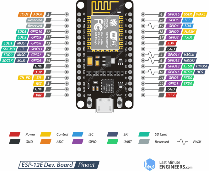
So you’re trying to use GPIO 1 & 3 to control the speed and direction of the motor, but the HW-588a used GPIO 5 and 0 to control motor A.
I think you’re confusing the “D” numbers screen printed onto the board with GPIO numbers.
Pete.
1 Like
I cannot thank you enough, it works!!
And for future reference, how do I know which digital pins translate to which GPIO?
If you think using a 9V battery may be dangerous, what would you recommend doing to step down the voltage?
Again, I really appreciate your help and you’ve now ended my frustration! For anyone using this to help them in the future, I got it to work by changing the int for MotorSpeed and Motor Direction to:
int MotorSpeed = 0;
int Motor Direction = 5;
There are tons of pinout diagrams on the internet, like this…
A small buck converter with a 5v output like this…
Pete.
1 Like
Thank You, I’m going to look into those. But out of curiosity, why is it not a good idea to use 9V? Is it a good idea in general to just not go near the max Voltage.
Also, when I run the code, openBlinds() should go one direction and closeBlinds() should be the opposite direction but when I run it, it only goes clockwise both times. Does HIGH and LOW not correspond to different directions of the motor, or am I not calling the functions correctly?
I’m not saying that it isn’t a good idea. It’s just something that I would never do.
As far as I’m concerned, these are 3.3v devices that have a voltage regulator circuit which is designed to accept a low-noise stabilised 5v supply and step that down to 3.3v. If you want to do something different then go ahead - it’s a personal choice.
My other concern would be that motors are noisy devices. They can create Back-EMF, and although the levels created will depend on the technology used, and brushless are generally far better, I’d still want some electrical isolation and smoothing on the supply rails if it were my device.
I’ve no idea, I’ve never used one of these controllers and I also don’t know what the capabilities and requirements of your motor are.
My next step would be to remove the jumper that powers the NodeMCU via the 9v battery and instead connect a USB cable to the NodeMCU and your computer. This will give you debugging capabilities via your serial monitor and will allow you to use serial print statements as a way of tracking program flow, variable values etc.
I’d also try experimenting with the motor and the battery and see what it’s capabilities are. I would have expected that a stepper motor, and a stepper motor controller, would have been a better choice for the project you’ve described.
One other thing, now that you’ve managed to get your motor moving - the use of delay() isn’t really compatible with Blynk. You should look at using BlynkTimer in timeout timer mode instead as your project progresses.
Pete
1 Like

