Controlling RF powerplugs: sending RF 433 signal correct

Hi

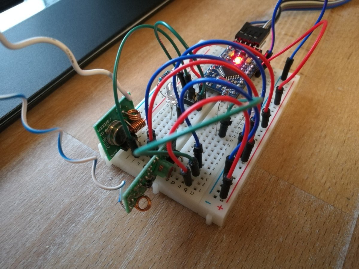
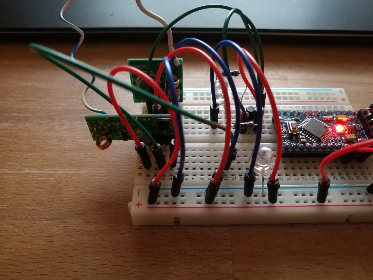
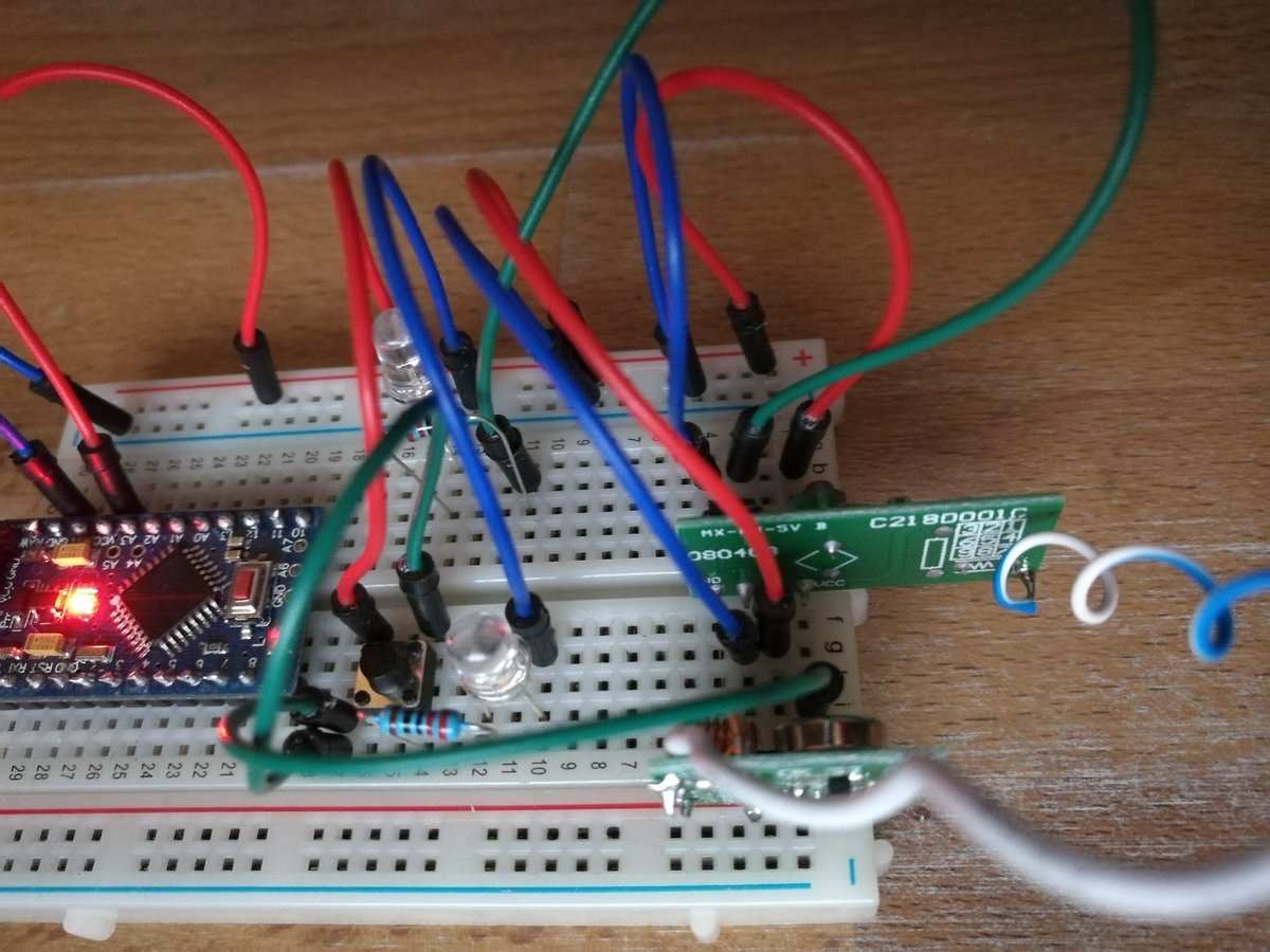
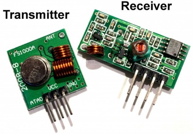
Im trying to mimic a RF remote to control a retail RF powerplug. (a Danish Sartano model number 50080).

I have not connected it to Blynk yet but will come when I get this right.
Though I have come quite far, but struggling with sending the signal in a correct way.

I have used a SDR usb dongle with the linux commandline tool rtl_433.

Using device 0: Generic RTL2832U OEM
Found Rafael Micro R820T tuner
Exact sample rate is: 250000.000414 Hz
Sample rate set to 250000.
Bit detection level set to 0 (Auto).
Tuner gain set to Auto.
Reading samples in async mode…
Tuned to 433920000 Hz.

Picking up the “on” signal from the remote:

*** signal_start = 573180, signal_end = 721237
signal_len = 148057, pulses = 282
Iteration 1. t: 203 min: 94 (134) max: 313 (148) delta 2221
Iteration 2. t: 203 min: 94 (134) max: 313 (148) delta 0
Pulse coding: Short pulse length 94 - Long pulse length 313

Short distance: 215, long distance: 570, packet distance: 1763

p_limit: 203
bitbuffer:: Number of rows: 5
[00] {151} 65 1d b8 32 8e dc 19 47 6e 0c a3 b7 06 51 db 83 28 ed c0
[01] {33} 2e 0f fa d3 00 : 00101110 00001111 11111010 11010011 0
[02] {33} 2e 0f fa d3 00 : 00101110 00001111 11111010 11010011 0
[03] {33} 2e 0f fa d3 00 : 00101110 00001111 11111010 11010011 0
[04] {32} 2e 0f fa d3 : 00101110 00001111 11111010 11010011

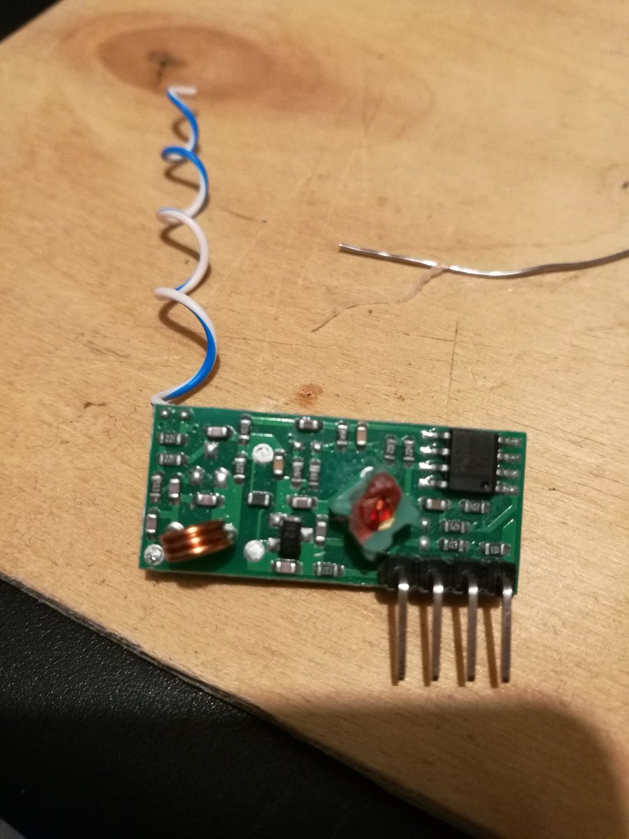
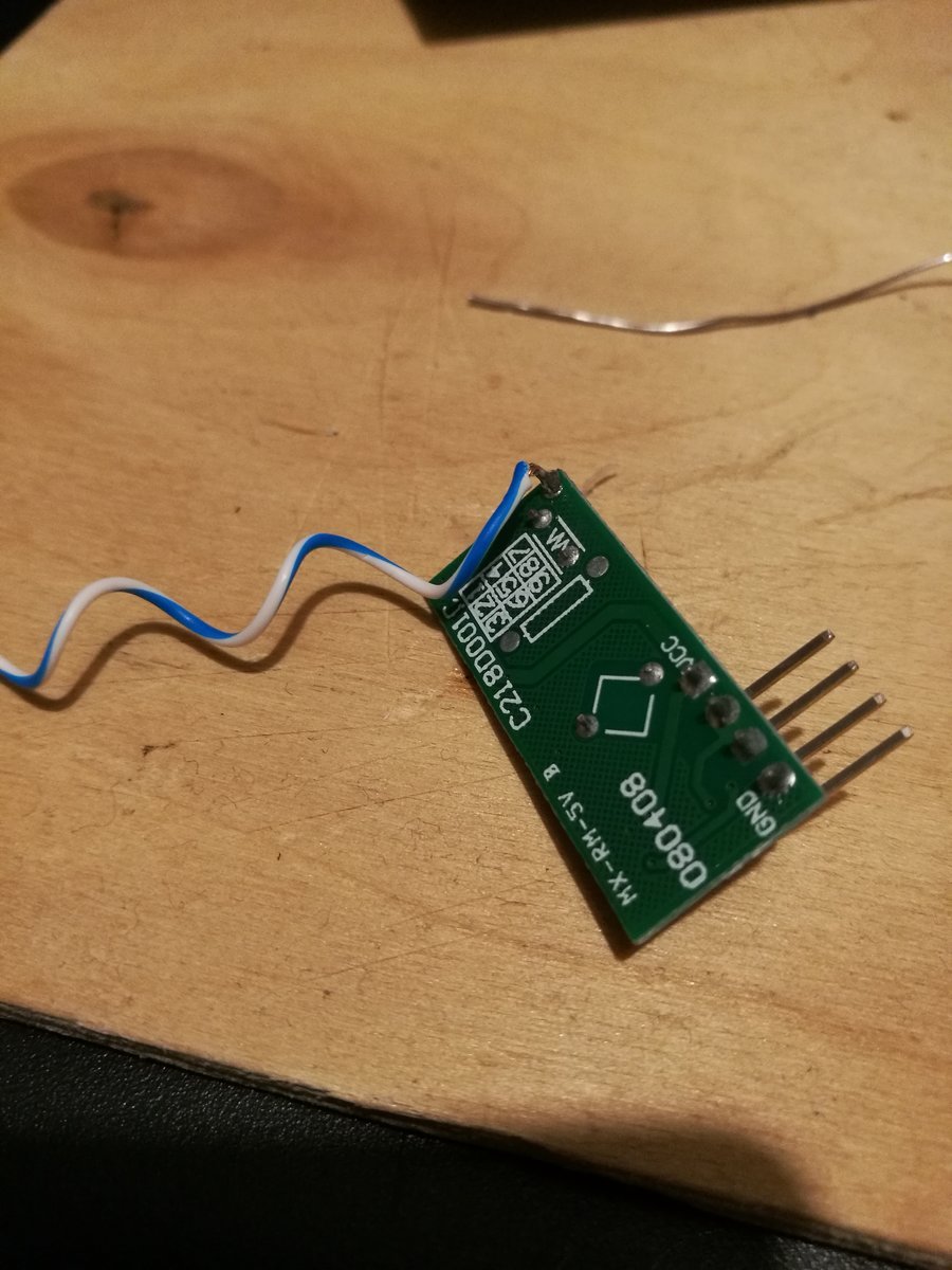
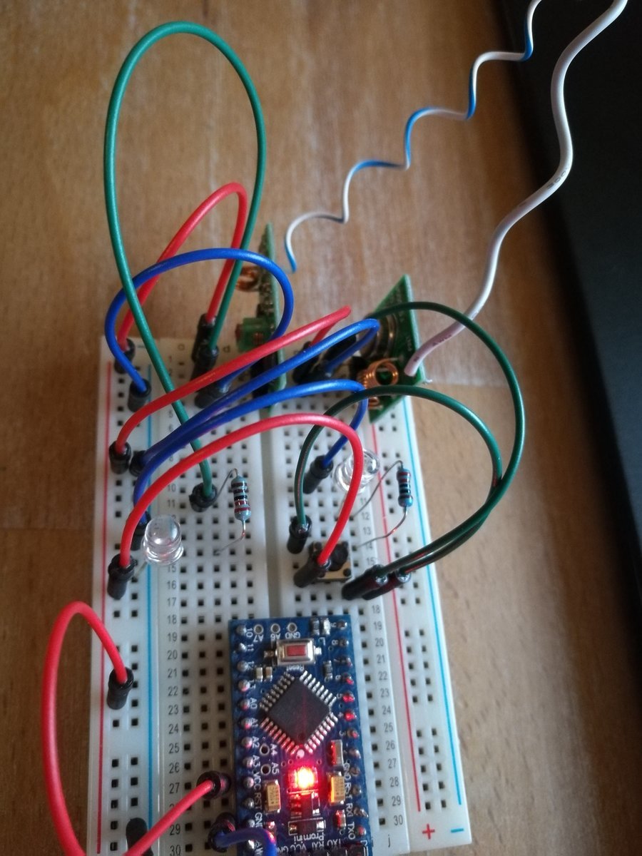
and trying to mimic it by the arduino pro mini 3.3v
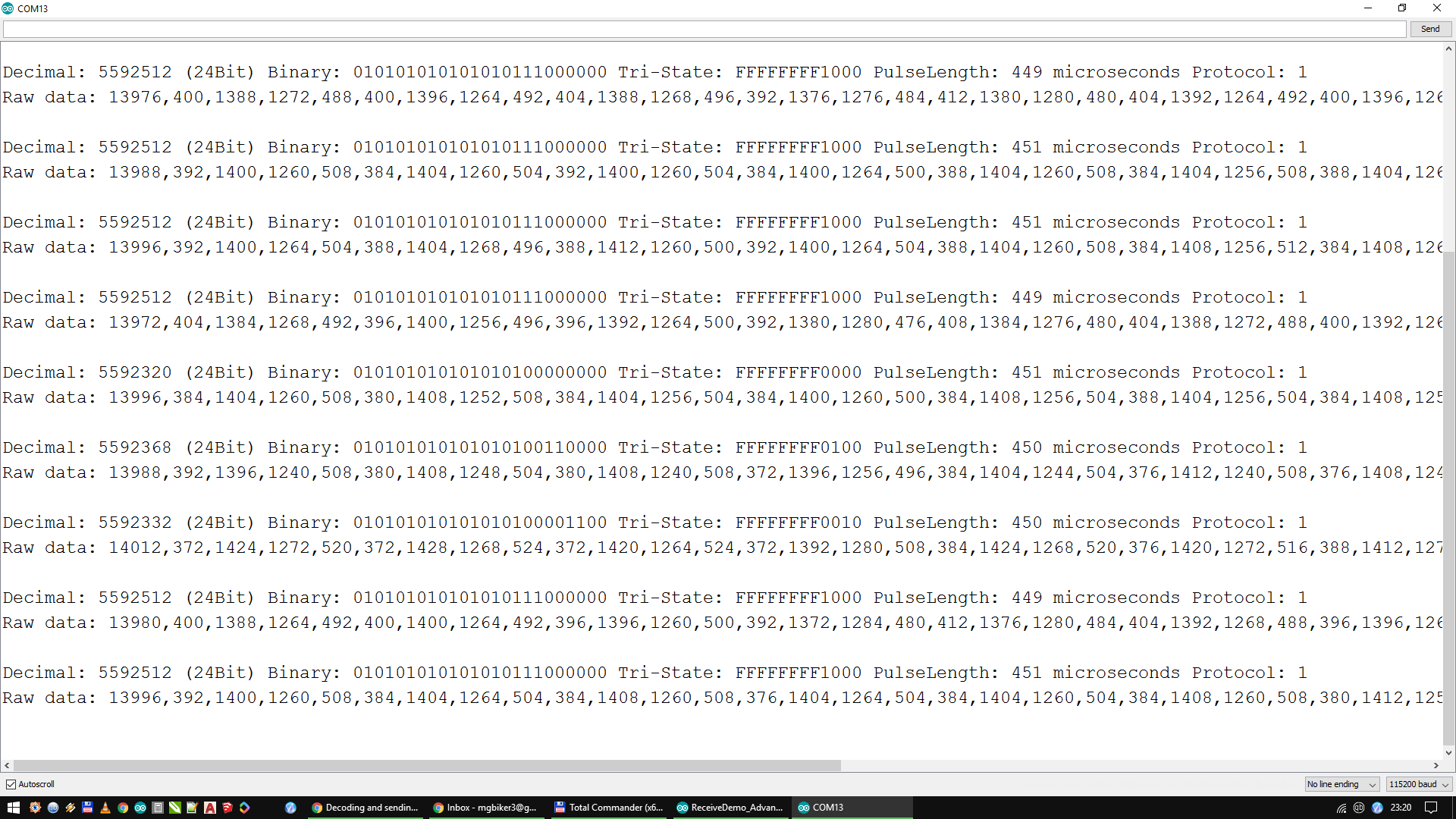
But the rtl_433 tool picks up the signal quite different, instead of 3-4 repeated signals, it picks it up as 13 signals.

*** signal_start = 2630409, signal_end = 2664289
signal_len = 33880, pulses = 33
Iteration 1. t: 205 min: 91 (14) max: 320 (19) delta 17
Iteration 2. t: 205 min: 91 (14) max: 320 (19) delta 0
Pulse coding: Short pulse length 91 - Long pulse length 320

Short distance: 107, long distance: 110, packet distance: 339

p_limit: 205
bitbuffer:: Number of rows: 14
[00] {1} 00 : 0
[01] {1} 00 : 0
[02] {2} 80 : 10
[03] {4} e0 : 1110
[04] {1} 00 : 0
[05] {1} 00 : 0
[06] {1} 00 : 0
[07] {1} 00 : 0
[08] {10} ff 80 : 11111111 10
[09] {2} 80 : 10
[10] {3} c0 : 110
[11] {2} 80 : 10
[12] {1} 00 : 0
[13] {3} c0 : 110

Must have something to do with bitbuffer I guess?

Extra info:
since the rtl_433 uses 250k sampelrate I have multiplied the min/max with 4.

signal_len = 33880, pulses = 33
Iteration 1. t: 206 min: 92 (14) max: 320 (19) delta 40
Iteration 2. t: 206 min: 92 (14) max: 320 (19) delta 0
Pulse coding: Short pulse length 92 - Long pulse length 320

If anyone know on how to move on, I’ll appreciate some help

my arduino code is this

#define rfTransmitPin 4
#define ledPin 13
     
 
void setup(){
    Serial.begin(9600);
    pinMode(rfTransmitPin, OUTPUT);
    pinMode(ledPin, OUTPUT);
          
 
    digitalWrite(rfTransmitPin, LOW);
    Serial.print("ready\n");
 }
 
  void loop(){
   
      transmitCode();
      Serial.print("transmitting ON signal \n");
  }
 
#define SHORT_WAIT  delayMicroseconds(336)  //min x4
#define LONG_WAIT   delayMicroseconds(1228) //max x4
#define TX_LOW      digitalWrite(rfTransmitPin, LOW)
#define TX_HIGH     digitalWrite(rfTransmitPin, HIGH)
#define OUTPUT_0    {TX_HIGH; SHORT_WAIT; TX_LOW; LONG_WAIT;}
#define OUTPUT_1    {TX_HIGH; LONG_WAIT;  TX_LOW; SHORT_WAIT;}
 
#define FRAME_SIZE        33
 
int code[] = {0,0,1,0,1,1,1,0,0,0,0,0,1,1,1,1,1,1,1,1,1,0,1,0,1,1,0,1,0,0,1,1,0};
 
void transmitCode() {

    
    digitalWrite(ledPin, HIGH);
 //for (int repeat = 1; repeat <= 3; repeat++)
 // {
   for (int i = 0; i < FRAME_SIZE; i++)
    {
       if(code[i] == 1)
       
        {
          Serial.print(code[i]);
          //OUTPUT_1;
          digitalWrite(rfTransmitPin, HIGH);
          delayMicroseconds(1228);
          digitalWrite(rfTransmitPin, LOW);
          delayMicroseconds(336);
        }
        else
        {
          Serial.print(code[i]);
          //OUTPUT_0;
          digitalWrite(rfTransmitPin, HIGH);
          delayMicroseconds(336);
          digitalWrite(rfTransmitPin, LOW);
          delayMicroseconds(1228);
        }
    }
    digitalWrite(rfTransmitPin, LOW);
    delayMicroseconds(200);
 // }
    Serial.print("\nwaiting \n");
    digitalWrite(ledPin, LOW);
    delay(10000);
 
    digitalWrite(ledPin, LOW);
 }

@tjohansen your post isn’t really Blynk related but there are some “RF guys” on this site. I believe your socket uses the same protocol as the Elro devices.

We are able to control Elro devices with our equipment even though we have never physically touched one.
There is one, well two now, “Elro” thread(s) on this site that might be useful.

Please don’t post code like that, it makes the place look untidy :slight_smile:

Fixed the arduino code

Do all Scandinavians put setup() and loop() in the middle of the #define statements?
Academic I guess.
P.S. I recognise the code.

2 Likes

naeh

used this example to get started

http://dani.foroselectronica.es/tag/rtl_433/

But here in this test it gives a better overview to have the #define’s related to the code the correct places.

Academic I guess

Im not a coder, just trying to learn a bit in playing with arduinos.

hello!
you can also try this method, explained in the article to record / playback the signal:


it is a very detailed tutorial, it was useful for me in some rf project.

:slight_smile:

thx for the tip, I will look into those.

tried the exsamples from that guide.

tutorial 2 “receive code”
gave a lot of noise and it picks up from the beginning and not reacting on the remote.
Or maybe too much noise to see it.

then I thought to test tutorial 4 “receive code and sendit again autocratically”
It couldnt receive it and send it again, think my remote signals are too tricky for this.

think it has something to do about line [00]

hello!

in last days, by chance i had again some project to do with rf modules, and i came across this instructable: http://www.instructables.com/id/Decoding-and-sending-433MHz-RF-codes-with-Arduino-/

it worked fine for me, actually it is much better than the other article i linked in older post. i think this is what you need. definetly worths a look!

thanks for tip I’ll look in to it.

In my quest for figuring out / “reverse engineering” the rf 433 signals from my cheap home powerplugs I have found this which looks interesting:

But at the same time I think my rf 433mhz receiver module is defect.
I have tried numerous variations and test schemes and I cant get it to show anything.

but what rf receiver are you using? can you post a picture?
and, i know it is a silly question, but are you using an antenna?
for me a ~17cm simple copper wire, set vertically worked the best.
i’m using some very cheap modules with the wire antenna, and they are working acceptable.

for example, sniffing a common, cheap, car remote control, using the mentioned rc-switch library, i got this:

It a RX/TX rf433 kit

the receiver has model name MX-RM-5V

But I have bought a new kit im waiting for.

see pictures.
I have tried a lot of rf 433 test sketchs and libraries. but also found a test guide to set them up to where when pushing button, TX sends and RX should lightup on a diode if it recieves, but it does not react to anything, though I can send, because my SDR tool can see it.
Maybe one problem but have read it only matters to distance… My mini pro runs in 3.3v and not 5v as recommended for the RX module.

source

yes, i use exactly the same module. my opinion is, that if it not works with the method described here http://www.instructables.com/id/Decoding-and-sending-433MHz-RF-codes-with-Arduino-/ or here: https://z4ziggy.wordpress.com/2014/06/27/rf-sniffer-open-gates-cars-and-rf-remote-controlled-devices-with-ease/

than:

1 - the module is defective (it is easy to verify with the tx module)
2 - the remote you are trying to use is not compatible with the receiver
3 - there is some strong 433mhz rf noise in your area (ham radio, etc)

in one of my current project, i also run an rx module on 3.3v, and indeed gives very reduced range (only few meters).

also, it depends on the voltage of the tx. i run these tx modules on 12v. if i also give 5v to the rx, i have around 12m in building with walls, and much more in open air.

i have checked the datasheet of the op-amp on the rx module, and it says min 3v, max 32v, if i remember correctly. so, probably 3.3v is way to low…

maybe i will try to feed the rx with 8v (i’m not sure what is the max voltage for the other components on the rx module) and use an opto coupler between the rx module and the wemos.